Download
1 / 39
480 likes | 1.61k Views
MICRO HYDROELECTRIC POWER PLANT WITH CHAIN TURBINE. Nguyen Minh Duy. Content. Overview about hydroelectric power plant Analysis chain turbine Governor using for chain turbine Work in the future. Electrical Energy. Potential Energy. Electricity. Kinetic Energy. Mechanical Energy.

E N D
MICRO HYDROELECTRIC POWER PLANT WITH CHAIN TURBINE NguyenMinh Duy
Content • Overview about hydroelectric power plant • Analysis chain turbine • Governor using for chain turbine • Work in the future
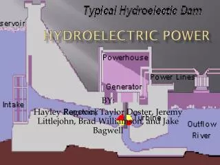
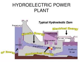
ElectricalEnergy PotentialEnergy Electricity KineticEnergy Mechanical Energy Hydropower to Electric Power
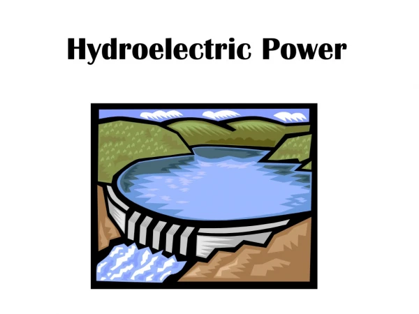
How Hydropower Works • Water from the reservoir flows due to gravity to drive the turbine. • Turbine is connected to a generator. • Power generated is transmitted over power lines.
How Hydropower Works (2) • A water turbine that cover the energy of flowing or falling water into mechanical energy that drives a generator, which generates electrical power. This is a heart of hydropower power plant. • A control mechanism to provide stable electrical power. It is called governor. • Electrical transmission line to deliver the power to its destination.
Vietnam Hydroelectric Potential (2) • Vietnam, the nation yearly average of rainfall is about 1,861mm. • There are more than 2,200 big-to-small rivers and streams. So Vietnam is rich hydropower resource. • Vietnam is agricultural country (agriculture: 20.1%). This is a goal to invest SHP.
Sizes of Hydropower Plants • Pico hydroelectric plant • Up to 10kW, remote areas away from the grid • Micro hydroelectric plant • Capacity 10kW to 300kW, usually provided power for small community or rural industry in remote areas away from the grid • Small hydroelectric plant • Capacity 300kW to 1MW • Mini hydroelectric plant • Capacity above 1MW • Medium hydroelectric plant • 15 - 100 MW usually feeding a grid • Large hydroelectric plant • More than 100 MW feeding into a large electricity grid
Micro Hydropower Systems • Many creeks and rivers are permanent, they never dry up, and these are the most suitable for micro-hydro power production • Micro hydro turbine could be a waterwheel • Newer turbines : Pelton wheel (most common) • Others : Turgo, Crossflow and various axial flow turbines
Impulse Turbines • Uses the velocity of the water to move the runner and discharges to atmospheric pressure. • The water stream hits each bucket on the runner. • High head, low flow applications. • Types : Pelton turbine, Turgo turbine
Reaction Turbines • Combined action of pressure and moving water. • Runner placed directly in the water stream flowing over the blades rather than striking each individually. • Lower head and higher flows than compared with the impulse turbines.
Chain Turbine • It is a gravity machine • It is built up of two parallel chain systems joint together at the chains with a series of buckets. • The flow rater entering the buckets is controlled by the water valve through a motor to open or close the valve. • Buckets fill full of water go down to bring to rotary sprocket system.
Analysis of the Chain Turbine • With flow rate is 1m3/s, and the head is 20m. • Assume H1=19m, H2=1m, the diameter of the sprocket is 1m.
Analysis of the Chain Turbine (2) • The gross power output: • Apply the principle of work and energy with the bucket of chain turbine: • The maximum speed of bucket • The angular velocity the sprocket would be • The rotational speed of the sprocket would be
Analysis of the Chain Turbine (3) • Number of buckets in chain turbine
Analysis of the Chain Turbine (4) • The power output is • The power out of the turbine shaft • The efficiency of the chain turbine is given by
Analysis of the Chain Turbine (5) • Rotational velocity of sprocket depends on the distance of between two shafts of turbine H1. • Rotational velocity of turbine shaft is slow, so it cannot directly connect with generator. It need a power transmission • Efficiency of chain turbine is low.
Advantages of Chain Turbine • It is run-of-river power plant. • Do not worry about the turbidity of water. • There is no danger of cavitations. • It is simple to construct, repaired and maintenance.
Disadvantages of Chain Turbine • The slow rotation of chain turbine leads to high speed ratios when connect to generator at 600 rpm – 1500 rpm. • This chain turbine operation is very noise. • Structure of turbine is very big
Governor • To maintain the generator at a constant 50Hz frequency, it is necessary to maintain the generator shaft at a constant rotational speed. • In the independent hydroelectric power plant, the rotational speed of the micro hydro power generator can be change when loads are added or subtracted from the electrical system.
Governor (2) • The system frequency can be maintained constant by eliminating the mismatch between generator and load. • Governor is to receipt the frequency signal from the output of generator. • And it is compared with standard frequency signal. • From these results, governor output signal is coming-out to control the valve of water at the entrance to the turbine.
Transfer Function Block Diagram of Hydro Plant • power system gain constant (Hz/p.u) • nominal starting time of water in penstock (s) • integral gain constant for servo system • proportional gain controller constant for servo motor
Governor Transfer Function • Chain Turbine transfer function • water starting time at full load • So transfer function of chain turbine is
Generator Transfer Function • Assume nominal load • Frequency 50Hz • The latter load assumption yields • So, the system gain constant and time constant are given by • The transfer function of generator
Transient responses of system for step changes in load, showing deviations in system frequency
Transient responses of system for step changes in load, (1.5kW) for different integral gain value, showing deviations in system frequency (1)
Transient responses of system for step changes in load, (1.5kW) for different integral gain value, showing deviations in system frequency (2)
Transient responses of system for step changes in load, (1.5kW) for different integral gain value, showing deviations in system frequency (1)
Transient responses of system for step changes in load, (1.5kW) for different integral gain value, showing deviations in system frequency (2)
Governor Discussion • It is more flexible than classical governor. • This governor effectively eliminate the frequency deviations due to load disturbances for different nominal loadings of the system • It is importance as the saved water can be used for irrigation.
Work in the Future • In China, YiuHwa Engineering Company is building a hydroelectric power plant with chain turbine to experiment and research with capacity 200kW. • This plant has two turbines and built with head 20m and flow rate 1.03m3/sec