Chapter 8 TDM, WDM, and CDM Systems
600 likes | 920 Views
Chapter 8 TDM, WDM, and CDM Systems. 8.1 Time-Division Multiplexing 8.2 Wavelength-Division Multiplexing 8.3 Definition of a DWDM System 8.4 Main Components Defined 8.4.1 Optical Transmitters 8.4.2 Wavelength Locker 8.4.3 Optical Receivers 8.4.4 Optical Cross Connects (OXC)

Chapter 8 TDM, WDM, and CDM Systems
E N D
Presentation Transcript
Chapter 8 TDM, WDM, and CDM Systems • 8.1 Time-Division Multiplexing • 8.2 Wavelength-Division Multiplexing • 8.3 Definition of a DWDM System • 8.4 Main Components Defined • 8.4.1Optical Transmitters • 8.4.2 Wavelength Locker • 8.4.3 Optical Receivers • 8.4.4 Optical Cross Connects (OXC) • Addressable Add/Drop Units • 8.4.5 Wavelength-Dependent Couplers • 8.4.6 Dispersion Compensation Devices
Chapter 6 TDM and WDM Systems • 8.5 Multiplexers and Demultiplexers • Thin-Film Filters • Fiber Bragg Gratings • Diffraction Gratings • Integrated Optical Devices • Fused Biconic Tapered (FBT) Devices • 8.6 Optical Add/Drop Multiplexers • 8.7 Optical Amplifiers • Pump Lasers • Gain Spectrum and Noise • Multi-Channel Amplifications • Other Optical Amplification Techniques
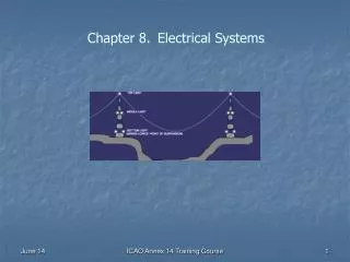
8.1 Time-Division Multiplexing Figure 8.01 In TDM systems, channels are divided into time-slots propagating at the same wavelength on the same fiber. • In TDM, the optical signal in a fiber is shared among a number of information channels by time slicing. • For a time slot, the signal is modulated with the 1st information channel; for the next time slot, the signal is modulated with the 2nd information channel, and so on.
8.1 Time-Division Multiplexing • Each communication path is assigned a specific time slot, a TDM channel, during which it is allowed to send data from the source to the user. No other source is permitted to transmit at the same time. • The multiplexer at the source end takes in data from the sources connected to it, and inserts packets of data from each into the fiber during the appropriate TDM time slot. • The demultiplexer at the other end must recognize the time slots, unload the data from each, and send it as a continuous stream to the corresponding user.
8.1 Time-Division Multiplexing • Forward error correction (FEC) can add up to several dBs of system margin. FEC adds extra check bits to the data payload, enabling occasional errors in the digital signal (1s and 0s) to be corrected without retransmission. • Polarization mode dispersion (PMD) describes how various polarization states of the signal propagate at different velocities along the fiber. • PMD is especially difficult to handle because it is a stochastic phenomenon: there are no known practical ways of eliminating its effects entirely.
8.2 Wavelength-Division Multiplexing • Rather than increasing the data rate to handle more information like a TDM system, a WDM system simply carries several optical signals, each at its own wavelength and each respecting the data-rate limitations applicable to the transmission system. • In WDM, one wavelength could be used for cable TV, another for telephony, another for Internet traffic, another for video-on-demand, four others reserved to a specific customer, eight others rented to five different customer, and so on.
8.2 Wavelength-Division Multiplexing • WDM technologies are particularly valuable in long-haul applications where greater bandwidth is needed, but wide area networks (WANs), potentially represent a large market by offering an economical way of making better use of the expensive base of installed cable. • These and other applications have led to dramatic increases in the number of wavelengths carried on a single cable and the resulting narrow channel spacing that characterizes a new class within the WDM domain: DWDM.
8.2 Wavelength-Division Multiplexing • Although the term wavelength division may imply transmission using any one of a limitless set of possible wavelengths, very practical limitations on available communications equipment presently limit DWDM use to a relatively narrow spectral band centered around 1550 nm. • TDM practices and specifications cannot be forgotten. A proper mix of TDM and WDM technologies is still appropriate for new and improved services through cost-effective, non-intrusive additions and upgrades to installed equipment.
8.3 Definition of A DWDM System • A DWDM system is much like a traditional TDM system, as shown in Figure 8.02. Fig. 8.02 Typical WDM system with add/drop and cross connect capabilities.
8.3 Definition of A DWDM System • The difference lies in the number of simultaneous optical signal channels carried by the fiber. In a basic TDM system, there is only one; in a DWDM system, there are several channels. We can think of a DWDM system as a number of parallel TDM systems, sharing fiber and equipment. • Basically, the optical part of a DWDM communications system consists of one or more laser transmitters, a multiplexer, one or more EDFAs, add/drop units (OADMs), the needed optical fiber (generally a cable), a demultiplexer, and the same number of receivers as transmitters, as shown in Figure 8.02.
8.4 Main Components Defined 8.4.1 Optical Transmitters • A transmitter for a single channel (wavelength) is typically made up of a distributed feedback (DFB) laser followed by a modulator, which is usually external to the laser especially when modulation rates are high. • Recent developments in integrated optics have led to attractive and cost-effective transmitter designs in which the laser chip, modulator, and a subsequent optical amplifier, are combined in a package. • Transmitter packages are now available that incorporate multi-lasers, multiplexers, and a booster amplifier, which is usually a semiconductor optical amplifier.
8.4.1 Optical Transmitters • A variable attenuator covering the band of the modulator is sometimes mounted next to a laser to tailor its power to a specific value. • This value is chosen to suit the characteristics of the first repeater down the transmission line, or when used with other wavelength transmitters to make sure that all transmitters combine to produce an equally flat spectral power distribution.
8.4.1 Optical Transmitters • In DFB laser, the usual two-mirror Fabry-Perot laser cavity is reduced and controlled, and selecting the exact lasing wavelength through optical feedback is accomplished by a longitudinal grating manufactured as part of the laser chip (see Figure 8.03). Figure 8.03 Simplified view of a DFB laser chip.
8.4.1 Optical Transmitters • Laser modulation used in low bit-rate systems -- modulating the laser drive current -- introduces too much chirp for long-haul transmission at the high rates of advanced WDM systems. • The option is to modulate the laser light externally (within or outside the source module), but this adds cost, circuit complexity, and optical loss, and can lead to state of polarization (SOP) management issues. • External modulators are generally based on switching technologies such as Mach-Zehnder interferometers or electro-absorption devices.
8.4.1 Optical Transmitters • Modulators based on integrated optics often use LiNbO3 or InP to achieve fast switching due to their high refractive index. • Withthe use of an EDFA or a semiconductor optical amplifier (SOA) after the modulator, WDM laser transmitters have demonstrated transmit powers of more than +16 dBm, just under the +17 dBm limit to meet the IEC 60825 Class IIIb laser safety designation.
8.4.2 Wavelength Locker • The successful operation of WDM and DWDM networks depends on the stability of the signal source. Wavelength lockers provide this stability. • Theusual wavelength locker consists of a pair of dielectric-layer optical filters, cascaded so both work with exactly the same source power. • One filter is tuned to a frequency just above the desired one, while the other is adjusted to a frequency that is the same interval below.
8.4.2 Wavelength Locker • The optical signals within the band pass of these two filters are detected and compared to provide an electrical control signal that indicates how far the source wavelength has drifted from its design value. Fig. 8.04 Simplified wavelength locker operating principle.
8.4.3 Optical Receivers • The receiver converts optical signals to an electronic form by detecting whatever modulation has been applied to the light signal and demodulating it. • Traditional optical techniques are used to couple light energy from a fiber to a detector, generally a photo-diode. • The resulting signal must be amplified electronically -- adding as little noise as possible -- within an electrical bandpass appropriate to the expected signal.
8.4.3 Optical Receivers • Two types of photodiodes are commonly used: positive-intrinsic-negative (PIN) diodes and avalanche photodiodes (APD). • The PIN device operates with standard low-voltage, logic power supplies (5 V), but it is less sensitive and covers a narrower bandwidth than the avalanche model. • High-speed PINs were used in 10 Gb/s and 40 Gb/s applications before the arrival of APDs. The latter is found mainly in long-haul applications, where its higher cost and greater circuit complexity is justified.
8.4.4Optical Cross Connects (OXC) • Early switching in fiber-optic networks involved converting the optical signal to an electronic one, performing the necessary switching operation, and reconverting the signal to optical -- a cumbersome and expensive process that involves switching speed limitations and reduces WDM operability. • Switches are used in WDM networks to divert signals to alternate routes in response to network difficulties, or to reroute signals to other networks. • The ability to switch signals easily is critical for the survival of the modern all-optical network. Optical cross-connect (OXC) routers are now essential to this survival.
8.4.4Optical Cross Connects (OXC) • The NxN switching fabric can be constructed from, electro-mechanical switches that perform switching by positioning tiny mirrors in the optical path. • The optical-mechanical approach has also been extended by micro-manufacturing or MEMS technology, which involves depositing many switching lenses and mirrors, and their actuators, on a silicon chip.
Addressable Add/Drop Units • The addressable add/drop device provides selective routing of DWDM channels, using optical switches combined with other components that can be based on fiber-switching or wavelength-switching technologies. • Using an addressable add/drop unit is to keep all routing within the optical transmission layer and to avoid having to opto-electronically convert transmission signals and then regenerate them.
Addressable Add/Drop Units • Arrayed-waveguide grating (AWG) represents a good example of this technology. A generic example of an OXC is shown in Figure 8.08. • In such a device, the wavelengths at each output depend on the wavelengths at the input. A control port can be added to allow selective wavelength routing. Fig. 8.06 Signal coming to the input port of the OXC is rerouted to other ports.
8.4.5 Wavelength-Dependent Couplers • Frequency-dependent parameters of optical devices that must be overcome to produce components, such as broadband couplers, can be used to produce components whose outputs are strongly wavelength-dependent. • For instance, take a wavelength-dependent coupler. Units are available to separate the 1310 nm and 1550 nm wavelengths commonly used in early WDM systems, or to combine the 980 nm or 1480 nm pump with the 1550 nm input signal into the Erbium-doped fiber in an EDFA.
8.4.6 Dispersion Compensation Devices • Optic components exhibit chromatic dispersion. Their index of refraction varies with wavelength, as does the propagation speed through them. • The most easily noticeable result is the broadening of transmitted optical pulses, which makes their error-free recovery more difficult as neighboring bits overlap. • A dispersion compensation device (DCD) is used to apply an equal but opposite dispersion to correct this pulse broadening. • The two most commonly used DCD types are dispersion compensating fibers (DCFs) and dispersion compensating gratings (DCGs). (see Figure 8.07 )
8.4.6 Dispersion Compensation Devices Figure 8.07 The broadening effect due to dispersion and its compensation.
8.5 Multiplexers and Demultiplexers • The output of each laser transmitter in a WDM system must be multiplexed and inserted into the first fiber cable span. The device used is called a multiplexer. • A similar device is used to extract the multiplexed channels at the receiver end of each link. It is called a demultiplexer. Figure 8.08 Typical representation of a multiplexer and demultiplexer.
8.5 Multiplexers and Demultiplexers • Multiplexing and demultiplexing functions both employ narrowband filters, cascaded and combined in other ways to achieve the desired result. • Particular techniques that have been used to perform such filtering include thin-film filters, fiber Bragg or bulk optic gratings, tapered fibers, liquid crystal filters, and integrated optics (phased array waveguides, AWG, or phasar).
Thin-FilmFilters • Thin-film filters consist of a number of layers of transparent dielectric materials of differing refractive indices deposited sequentially on an optical substrate. • One can use this internal interference to produce a filter that will pass any desired range of wavelengths and reflect the others (Figure 8.09). Figure 8.09 Incident wavelength I1 is reflected I2 at the same angle, and I3 is transmitted at a lower angle.
Thin-FilmFilters • In multi-stage units for multi-channel use, the beam reflected from each filter is the input for the next stage; thus, alignment is extremely critical. Fig. 8.10 Example of a cascaded thin-film filter for multi-wavelength demultiplexer.
Fiber Bragg Gratings • FBG is essentially an optical interferometer built right inside a fiber. If a glass fiber is doped with a suitable substance -- Ge is commonly used -- its refractive index can later be modified by exposure to ultraviolet light. If this exposure occurs in an appropriate periodic pattern, the fiber becomes a grating. • If the pattern is not periodic and varies monotonically (i.e., is "chirped"), the fiber grating can be used to compensate for chromatic dispersion in a fiber link, or to correct the frequency-broadening chirp of laser sources used under certain conditions.
Fiber Bragg Gratings • One common application involves an ADM with one or two optical circulators, as shown in Figure 8.11. • On the drop side, the circulator recovers the reflected wavelength and sends it to the drop port. • On the add side, the circulator recombines a new transmission signal at the same wavelength as that at which it was dropped. Figure 8.11 The fiber Bragg grating drop on a specific channel from the transmitted signal.
Diffraction Gratings • For each wavelength of incident light, there is an angle for which light waves reflecting from individual grating lines will differ in phase by exactly one wavelength. • At this angle, the contribution from each line will add constructively, so this will be the angle of maximum transmission for that specific incident wavelength. Fig. 8.12 The incident light is divided into all primary wavelength 1, 2, …, N.
Integrated Optical Devices • Integrated optical wavelength multiplexing / demultiplexing devices are the optical equivalent of integrated electronic circuits. • Typically, they consist of optical waveguides-core material surrounded by cladding material-layered onto silicon or LiNb substrates using many of the techniques adopted by the large-scale integration manufacturers. • The end result is a small package containing many optical components-usually interacting-that can be manufactured in significant quantities using totally automatic techniques.
Fused Biconic Tapered (FBT) Devices • In its simplest form, the biconic tapered coupler consists of a pair of single mode optical fibers that have been fused together lengthwise. • Signal light transmitted in a fiber-core mode that arrives at the fused region from one of the fibers on the left-hand side is redistributed into a variety of cladding modes as it crosses the joint. • As the fibers once again separate, cladding modes reconvert to core modes in each of the output (right-hand side) fibers. The result is an almost loss-less coupler or splitter.
Fused Biconic Tapered (FBT) Devices • If two such devices are connected in series (Fig. 8.13), the input energy is split between the two outputs, depending on wavelength, with a periodicity that is set when the device is manufactured. • Two frequencies that are present together on an input fiber can leave the device on separate fibers (the 2nd input fiber is not used). Figure 8.13 The fused fiber redistribution the input signal to the device.
8.6 Optical Add/Drop Multiplexers (OADMs) • Add/drop multiplexers are assembled using various spectral separation techniques to combine multiple optical signals onto a single transmission medium or to extract these signals after transmission. • In many parts of a network, one may not want to combine or disassemble the entire channel structure, but merely add a single channel to it or extract a single channel from it with an add/drop multiplexer. • An optical add/drop multiplexer performs this operation without the need to convert the signalsin all the channels to electrical form and back again.
8.6 Optical Add/Drop Multiplexers (OADMs) Figure 8.14 Typical representation of on OADM device.
8.7 Optical Amplifiers • An Erbium-Doped Fiber Amplifier (EDFA) consists of a length of erbium-doped fiber, so that it can convert energy from separately provided pump radiation to the wavelengths applied as signals, thus effectively amplifying them.
Pump Lasers • EDFAs must be pumped to amplify the incoming signal. Both 980 nm and 1480 nm lasers are suitable for EDFA pumping • Both 980 nm and 1480 nm wavelengths correspond to the energy levels of excited ions and can be well absorbed by the erbium-doped fiber. • Several pumping schemes, shown in Figure 8.16, are possible at either wavelength.
Pump Lasers Figure 8.16a-b-c: Typical EDFA designs with various pumping schemes; Figure 8.16d: using a dispersion compensation device (DCD).
Pump Lasers • The forward pumping direction provides the lowest noise. In fact, the noise is sensitive to the gain and the gain is the highest when the input power is the lowest, as is the case close to the input of the EDFA. • Backward pumping provides the highest saturated output power, as shown in Figure 8.17. Figure 8.17 Gain performance regions of an EDFA.
Pump Lasers • Pumping at 1480 nm is usually used in the reverse direction and 980 nm pumping in the forward direction to make the best use of the strengths of each. • The 1480 nm pump has a higher quantum efficiency but a somewhat higher noise figure, whereas the 980 nm pump can provide a near quantum limited noise figure. • Bidirectional pumping has the advantage that the population inversion, and hence the small-signal gain, is relatively uniform along the entire amplifier length.
Gain Spectrum and Noise • Typically, a single-stage pumped EDFA can provide a maximum of about +16 dBm output power in the saturation region or a noise figure of 5 to 6 dB in the small-signal region. • A typical EDFA has a small-signal gain that is not uniform across the spectrum. There is a broad peak in gain at 1535 nm and a relatively flat zone from 1540 nm to 1560 nm. • It is difficult to achieve high gain, low noise, and high pumping efficiency simultaneously. The limitation is mainly imposed by the ASE traveling backward toward the pump and depleting the pump power. An internal isolator can reduce this problem.
Gain Spectrum and Noise • The gain spectrum of EDFA doped with Ge is quite broad and has a double-peak structure. • The addition of Al to the fiber core broadens the gain spectrum even more. • The gain spectrum of alumino-silicate glasses has roughly equal contributions from homogeneous and inhomogeneous broadening mechanisms, contributing up to 35 nm. • The gain spectrum of EDFA depends on the amplifier length because both the absorption and emission cross sections having different spectral characteristics.
Gain Spectrum and Noise • Various techniques have been proposed to flatten the gain and expand the DWDM amplification window to 40 nm or more. • Gain flattening is also necessary to eliminate the distorted amplification of signals through cascaded in-line EDFAs. • There are devices which stretch the gain window to about 1610 nm, providing the capability for bidirectional DWDM transmission in different non-interfering windows, and also potentially relaxing the requirements for more densely packed DWDM.
Multi-Channel Amplifications • Today's EDFAs use internal components to promote reliable operation. Such components include isolators to suppress the build-up of back-propagating ASE, to prevent sensitivity to any reflections from a downstream in-line EDFA, or to prevent any residual pump energy emanating from this downstream EDFA. • Other components may include dispersion compensation elements, especially between the stages of a double-stage EDFA, to equalize the propagation delay between the various wavelengths in a DWDM multichannel signal.
2nd Active Stage Counter-pumped 1st Active Stage Co-pumped Er3+ Doped Fiber Er3+ Doped Fiber Output Signal Input Signal Optical Isolator Optical Isolator Optical Isolator PUMP PUMP Multi-Channel Amplifications