STS track recognition by 3D track-following method
110 likes | 267 Views
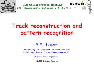
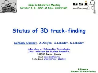
CBM Collaboration Meeting October 6-8, 2004 at GSI, Darmstadt. STS track recognition by 3D track-following method. Gennady Ososkov , A.Airiyan, A.Lebedev, S.Lebedev, E.Litvinenko Laboratory of Information Technologies Joint Intstitute for Nuclear Research, 141980 Dubna, Russia

STS track recognition by 3D track-following method
E N D
Presentation Transcript
CBM Collaboration Meeting October 6-8, 2004 at GSI, Darmstadt STS track recognition by 3D track-following method Gennady Ososkov, A.Airiyan, A.Lebedev, S.Lebedev, E.Litvinenko Laboratory of Information Technologies Joint Intstitute for Nuclear Research, 141980 Dubna, Russia email: ososkov@jinr.ruhome page: www.jinr.ru/~ososkov G.Ososkov STS track recognition
Fast track recognition in non-uniform magnetic field Our goal: is to recognize all tracks (including secondary ones) of any STS events by hits measured on seven STS stations taking into account the magnetic field non-homogeneity. The algorithm should be stable in respect to initial vertex coordinates and STS geometry. 3D view of a typical STS simulated event
The track recognition procedure is accomplished in 3D space on both X-Z and Y-Z projections simultaneously Y-Z and X-Z projections of the same event. Hits are marked as blue points The procedure alternates between both views predicting a track position on the next station and searching for hits in the vicinity of the predicted position. It is performed in two stages.
Stage 1. Starting from the middle of the target area we connect this point sequentially with all points on the first station in Y-Z view, where tracks are close to straight lines. Each time we prolong the straight line driven via these two points to the plane of the second station Then we set aside from the crossing point an asymmetrical corridor and look for all points appeared in this corridor. Then for each of these found points and two on sections previous we draw in X-Z projection a parabola which is prolonged to the next station. Since several prolongations can happened, we set aside corridors from each of pointpredicted on the third station. Then coming to the Y-Z view we set also a corridor aside of the corresponding prediction on the third station and look for hits in it. Prediction and search in YoZ view Prediction and search in XoZ view
Obvious weakness of this approach consists of its dependence on the vertex initialization. So starting with the primary vertex we can recognize only 10% of secondary tracks. In order to find the rest of them we should sequentially remove found track points and start from other vertex positions somewhere between stations An enlarged fragment of the previous figure
The main trick, guaranteed the final track-finding efficiency on the level of 91-94% depending on the track momentum, consists of the very careful preliminary calculations of the table with limits for those corridors depending on the station number and the sign of the particle charge. This table was calculated by statistics obtained by many thousands simulated events.Since the conventional approach to use symmetrical 3σcorridors had failed being too inefficient, we use the distributions of deviations between real hit positions and their predictions by prolonging straight line or parabola for all seven stations. Examples of those distributions for XoZ views on the 4-th and 7-th stations or for YoZ views on the 4-th and 6-th stations Pay attention to theirasymmetryand sizes growingfrom mkm to sm
Stage 2.Having tracks found on the first stage we make a selection on the basis of the following criterion: each point can belong to the only one track. So any track with one or more points belonging to some other track must be rejected Other tricks:Local fitting.3 points were kept on a track to fit a straight line or parabola. Attempts to use 4 or 5 points did not give any gain in accuracy due to multiple scattering. If the speed of the algorithm will be not important, Kalman filter could improve the prediction accuracy. Vertex positioning improvement.Although the algorithm has shown its stability to minor vertex shifts, the option exists to estimate the vertex position after the first run on the basis of several reference tracks. Then in the second run all track-following process is recalculated with the improved vertex position. One more way to simplify tracking in YoZ view consists of stretching of measured coordinates proportional to the station positions. Yk(new) = Yk*(z7/zk) . Magnified fragment However it has failed due to secondary tracks and magnetic field non-homogeneity.
Robust formalism of vertex finding We represent a track in YoZ projection as a straight line: and its XoZ projection as a parabola: where are tracks parameters. To find a vertex as a point closest to all tracks projections in YoZ and XoZ planes, we minimize through (y,z) and (x, z), respectively, the following functionals: where wiis Tukey’s bi-squared weight of the i-th track, are its parameters, σ and εi are to be recalculated on each iteration, εi is the space distance from the current vertex position to the i-th track. 5-9 iterations are needed to get the solution of the 3-d degree equation by Kardano formula. n is the number of tracks
Preliminary results Efficiency vs. momentum Average number of ghosts is 1.62 per event (we consider as a ghost is a track that has at least one wrongly found point)
What to do next 1. Prediction improvement • As one can see from figures with corridor distributions (for the “old” geometry) , a corridor on the 4-th station is 25 times more narrow then on the 5-th station and 30 times then on the 6-th station. That is due to • 1. multiple scattering; • 2. too simple track fitting model; • STS geometry is maybe not optimal. • However with the data generated using CVC dated 5.10.04 we already obtained much narrower corridors and 3% better efficiency
What to do next (continue) Therefore, for further decreasing our corridors we should apply, first, the Kalman filter technique and , then, more elaborated track model (say, Runge-Kutta solution for the real map of magnetic field) • Vertex positioning improvement. The Kalman filter*) applying for the better vertex estimation is planned. • More elaborated track selection criterion is planned to improve both efficiency and the ghost rate Program status: the library for evaluation of the algorithm efficiency executed starting from the root file generated by the current framework CVS is created and tested at GSI Linux system. ________________________________________________ *) Program implementing Kalman filter written by Sergey Baginyan is supposed to be used