Download
1 / 63
630 likes | 819 Views
Distributed Systems. Session 3: Communication In Distributed Systems Christos Kloukinas Dept. of Computing City University London. 0 Outline & Review.

E N D
Distributed Systems Session 3: Communication In Distributed Systems Christos Kloukinas Dept. of Computing City University London
0 Outline & Review • Last session we have discussed an object-oriented component model. Common properties of similar components are modeled as object types (interfaces). Services offered by distributed components are modeled as operations of these object types. • This session, we are going to consider the following problem: What communication primitives are needed in a distributed system and how are they used to implement service requests?
0.1 Last session’s Learning Outcomes • Why do we need a component model? • What are the primitives of the CORBA object model? • What is OMG/IDL? • What are the strength and weaknesses of the CORBA approach?
0.2 WHY? • Distributed Systems consist of multiple components. • Components are heterogeneous. • Components still have to be interoperable. • There has to be a common model for components that expresses • component states, • component services and • interaction of components with other components.
0.3 Primitives Of CORBA Object Model?? • Components objects. • Component state object attributes. • Usable component services object operations. • Component interactions operation execution requests. • Component service failures exceptions.
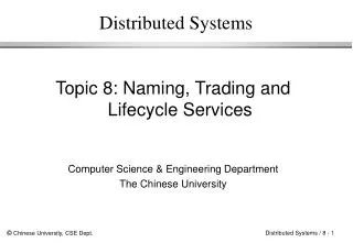
C C C++ C++ Java Java Ada Ada Cobol Cobol Smalltalk Smalltalk IDL IDL IDL IDL IDL IDL 0.4 CORBA && OMG IDL Client Server CORBA Object Implementations Client Stub Server Skeleton Request Object Request Broker CORBA Services
0.5 The OMG Interface Definition Language • OMG/IDL is a language for expressing all concepts of the CORBA object model. • IDL is a 'contractual' language that lets you specify a component's (object's) boundaries and its interfaces with potential clients • CORBA IDL is language neutral and totally declarative (i.e does not define implementations details) • Provides operating system and programming language independent interfaces to all services and objects that resides on the CORBA bus. • Different programming language bindings are available. (We’ll work with JAVA)
0.6 Problems of the Model • Interactions between components are not fully defined in the model. • No concept for abstract or deferred types. • Model does not include primitives for the behavioural specification of operations. • Semantics of the model is only defined informally. Bastide R. et al.: “Petri Net Based Behavioural Specification of CORBA Systems.” Lecture Notes in Computer Science, Vol. 1630: Application and Theory of Petri Nets 1999, 20th Int Conference, ICATPN'99, Williamsburg, Virginia, USA, pp. 66-85. Springer-Verlag, June 1999.
Objective For this session • In this session, we are going to consider the following questions: • What communication primitives are needed in a distributed system? • How are these primitives used to implement service requests?
Outline 1 Communication: Introduction 2 Communication Primitives 3 Client/Server Communication 4 Group Communication 5 Summary
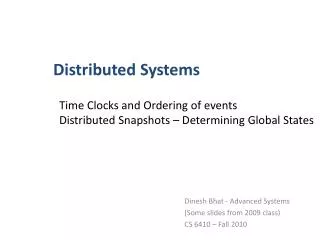
Address space 1 Address space 2 P1 P2 Operating system Operating system 1.0 Introduction • No shared memory in Distributed System • So all communication based on message passing • Consider Process/ Component P1 communicating with P2, what is required? network
1.1 Introduction • P1 builds a message in its address space • Executes a system call • Operating system fetches message and transmits over network to P2 • Issues & agreements?? • Meaning of bits being sent ? • Volts being used to signal 0-bit, 1-bit ? • which was the last bit sent? • Error detection? • How long are numbers, strings etc? • How are they represented?
1.2 Communication Standards • Need for standards to deal with numerous levels and issues in communication • OSI Reference Model developed by (ISO) for open systems • Identifies various levels, assigns standard names and defines functionality • Defines PROTOCOLS • A protocol is an agreement between communicating parties on how communication is to proceed
1.3 Protocols • To allow a group of machines to communicate over a network, all must agree on protocols to use • OSI distinguishes two types of protocols • Connection-oriented (like in telephone) • Connectionless (postal service) • In OSI model, communication is partitioned into 7 layers • Each layer deals with one aspect of communication
Application Presentation Session Transport Network Data link Physical 2 Communication Primitives The ISO/OSI (International Organization for Standardization/ Open Systems Interconnection) Reference Model: • Need for standardization of the communication between hosts built by different organizations. • Each layer builds on abstractions provided by the layer below.
Presentation & Transport Application Presentation We are going to review two layers of the model that are important for the implementation of service requests in general, and CORBA operation invocation requests in particular Session Transport Network Data link Physical
Transport Layer Application • Level 4 of ISO/OSI Reference Model • Concerned with the transparent transport of information through the network • Responsible for end-to-end error recovery and flow control. It ensures complete data transfer • It is the lowest level at which messages (not packets) are handled. Messages addressed to communication ports • Protocols maybe connection-oriented or connectionless • Two facets in Unix: • TCP and • UDP Presentation Session Transport Network Data link Physical
2.8 ISO/OSI Transport Layer • The transport layer implements transport of data on the basis of some network layer (the network layer itself may be implemented as the Internet Protocol (IP) or OSI's X-25 protocol). • There are a number of transport layer implementations, though the most prominent ones are TCP and UDP that are available in virtually all UNIX operating system variants. • TCP is connection-oriented. This means that a connection between two distributed components has to be maintained by the session layer. • UDP is connectionless. The session layer is not required when transport is UDP based.
2.9 Transmission Control Protocol: TCP • TCP provides bi-directionalstream of bytes (unstructured data) between two distributed components. • A component using TCP is unaware that data is broken into segments for transmission over the network. • UNIX rsh, rcp and rlogin are based on TCP. • Reliable, often used with unreliable network protocols • (e.g., a telephone line used with a Serial Line Internet Protocol (SLIP)). • Or with internet Protocol (IP) . Applications such as ftp that need a reliable connection for a prolonged periods of time establish TCP connections. • Slow! As the two ends connected by the stream may have a different computation speed, • TCP buffers the stream so that the two processes are (partially) decoupled.
2.11 TCP Operation • When a data segment is received correctly at destination, an acknowledgement (ACK) segment is sent to the sending TCP • ACK contains sequence number of the last byte correctly received incremented by 1 • The network can fail to deliver a segment. If the sending TCP waits for too long for an acknowledgement, it times out and re-sends the segment, on the assumption that the datagram has been lost • Then network can potentially deliver duplicated segments, and can deliver segments out of order. TCP buffers out of order segments or discards duplicates, using byte count for identification
2.12 User Datagram Protocol: UDP • UDP enables a component to pass unilaterally a message (datagrams) containing a sequence of bytes with restricted length (packets) to another component. • Connection-less (like a postal service) • UNIX rwho command is UDP based • UDP is unreliable because it does not detect messages that are lost completely.It depends on lower layers’ reliability (e.g. optical wire with Asynchronous Transfer Mode (ATM) network implementations). • Or used for applications where reliability is not a concern • e.g. DNS, streaming multimedia, Voice over IP (WHY???) • Fast & efficient: It does not spend any resources on error-detection and correction, no connection overhead, no waiting for ACK. • Application can opt to use UDP where its prepared to implement its own reliability
2.13 Transport Layer: Sockets • Transport layer implementations are available (in all UNIX workstations and servers as well as various Microsoft OS) in the form of sockets. • Sockets are identified by an Internet domain name and a port number. • Sockets of type SOCK_STREAM provide the programming interface to TCP. • SOCK_DGRAM to UDP (sento, recvfrom).
Presentation Layer • At Application layer: Complex Data types Application Presentation Session • How to transmit complex values through transport layer Transport Network • Presentation Layer issues: • Complex data structures • Heterogeneity Data link Physical
2.14 ISO/OSI Presentation Layer • There is a considerable mismatch between the complex types used at the application layer, such as records, lists and unions of other complex types in IDL, and those that can be transported by TCP and UDP. • A further complication arises from the fact that atomic types are represented differently on different hardware platforms. • The task of the presentation layer is to resolve these heterogeneity and transform complex data structures into forms that are suitable for transport layers, such as TCP and UDP.
2.16 Heterogeneity • Different hardware and operating system platforms use different representations for elementary data types such as integers and characters: • Most modern operating systems represent 16-bit integers as two bytes, where the most significant byte comes first. Older machines, such as IBM mainframes, represent these integers exactly the other way around. • There are also different encodings for character sets. Characters may be encoded as 7-bit ASCII, in the ISO 8-bit character set or in the emerging 16-bit representation, which accounts for the representation of Asian characters as well. • Distributed operating systems resolve these differences within the presentation layer so as to enable heterogeneous components to communicate with each other.
2.17 Example: Endianness • Big endian means that the most significant byte of any multibyte data field is stored at the lowest memory address, which is also the address of the larger field.(Sun’s SPARC, Motorola 68K, JAVA Virtual Machine. • Little endian means that the least significant byte of any multibyte data field is stored at the lowest memory address, which is also the address of the larger field. (Intel 80x86 processors
2.18 Solution Heterogeneity • There are different approaches. One is to convert data during marshalling into a common/shared and well defined representation. An example of this is Sun’s External Data Representation (XDR), which is used in most Remote Procedure Calls (RPC). • For each platform, provide a mapping between common and specific representation • Another approach is the Abstract Syntax Notation ASN.1 that was standardised by the CCITT. It provides a notation for including the type definition together with each value into the marshalled representation.
Marshalling: Disassembles a data Structure into transmittable form Unmarshalling: Reassemble the complex data structure Complex Data Structures Class Person { private int dob; private String name private long id public String marshal(){ return id+”,”+name.size+”,”+name; ); } }
2.15. Marshalling • Marshalling flattens complex data structures into a transportable representation, usually a stream of bytes, which may be split into a sequence of messages if necessary. • The stream of bytes not only contains the data itself, but also meta-information, such as the length of a certain entry, or an encoding for its types. • The presentation layer at the receiving component then performs the reverse mapping, which is called unmarshalling. It reconstructs the complex type from data and meta data that is included in the stream received. • Note, that marshalling in practice is rarely programmed manually. It is being taken care of by the distributed operating system, such as an ORB in CORBA.
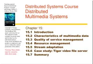
5 “Smit” “h___” 7 “Lond” “on __” 1934 2.19 XDR Message • Describes serialised byte streams • streams can be passed across network Length of sequence Smith • Arrays, structures and strings represented as sequence of bytes with specified length • Characters are ASCII code • Specify which end of each is MSB Length of sequence CARDINAL The message is ‘Smith’,’London ’,1934
2.20 Communication Patterns • Basic operations: send and receive messages • Message delivery: Synchronous or Asynchronous (*) • Messages are used to model: Request and Notification. (*) Meaning completely different from a/synchronous systems…
2.29 Request request receive(...) send(...) receive(...) ... send(...) reply Requester Provider • Bi-directional communication. • The sender expects the delivery of a result from the receiver. • Requester receives reply message. • Request/reply messages contain marshalled parameters/results.
2.21 Synchronous Communication • The sender invokes the send operation.The message is buffered in the local transport layer. • The message is sent by the local transport layer to the remote transport layer. • The message is received by the transport layer of the remote component and is buffered there. • The receiver invokes the receive operation to obtain the message. This causes an acknowledgement to be sent to the sender. • The acknowledgement is received by the sender.
1.3 Synchronous Communication (1) (2) (3) (4) (5) sender blocked send Transport Layer ackn receive receiver blocked Time
P1 Waits-for P2 2.23 Communication Deadlocks • Components are mutually waiting for each other. • It is hard to prove whether or not a system is deadlock-free and most distributed operating systems therefore do not do much about them and leave it to the designer to avoid them. • To avoid deadlocks: Waits-for relation has to be acyclic! P1: send() to P2; receive() from P2; P2: send() to P1; receive() from P1;
2.28 Notification send(...) receive(...) Notifier Notified • Uni-directional communication. • Message contains marshalled notification parameters. • The sender informs a receiver about a certain incident.
2.25. Asynchronous Communication • With asynchronous message delivery, the sender does not wait until the receiver has acknowledged the receipt of the message delivery, but continues as soon as the message has been passed to the local transport layer. • It may be delayed still, if message buffers of the transport layer are exhausted.
1.3 Asynchronous Communication (1) (2) (3) (4) sender send Transport Layer receive receiver blocked Time
The sender and receiver are decoupled and do not depend on each other. This usually results in a higher degree of concurrency between sender and receiver and increases the overall distributed system performance. The most important advantage is probably that the system is less likely to run into a deadlock. The sender does not know whether or not the receiver has actually received the message. Asynchronous delivery can therefore not reasonably be used together with unreliable transport layer implementations. Additional overhead is required if the message order has to be maintained. 2.26 Asynchronous Communication Pros and Cons
3.0 Client/Server Communication • The client/server model underlies almost every distributed system. Hence it is important to understand the principles of client/server communication. • Qualities of service. • Request protocol (R). • Request Reply protocol (RR). • Request Reply Acknowledgement protocol (RRA).
3.1 Quality of service – Client/Server • Exactly once: The service is executed once and only once. • At most once: The service request may or may not be or have been executed. If the service is not executed the client is being informed of the failure. • At least once: The call may be once or more than one time. • Maybe: It is neither guaranteed that the service has been executed nor is the client informed of failure occurrences should there be any.
3.2 Request Protocol • If the client can cope with the “maybe” quality of service, the client may not want to wait for the server to finish the service. This protocol, however, is unsuitable if the service has to return data or the client has to know what happened to the service execution. • The advantages are that • there is only one message involved thus the network is not unnecessarily overloaded and • The client can continue execution as soon as acknowledgement of message delivery has been returned. (FROM WHOM? A/Synchronous send…) execution request send(...) receive(...) exec op; Client Server
3.3 Request/Reply Protocol • To be applied if client expects result from server. • Client requests service execution from server through request message. • Delivery of service result in reply message. • If the reply message is not received after a certain period of time this can have many reasons (the server has not finished the execution yet; the reply message has been lost). • Servers therefore keep a history of reply messages and clients may resend the request and the server then resends the reply. request send(...) receive(...) receive(...) exec op; send(...) reply Client Server
3.4 RRA Protocol • Depending on the amount of client/server communication cycles, the maintenance of a history may involve a serious overhead! • The RRA protocol is designed to limit this overhead. • RRA adds to RR an additional acknowledgement message which is sent by the client as soon as a reply has been received. • The receipt of an acknowledgement message enables the server to dump the reply message of that communication cycle (and all previous non-acknowledged replies). request send(...) receive(...) send (...) receive(...) exec op; send(...) receive(...) reply ackn Client Server
RR & RRA – Quality of Service? • Request provides is for Maybe QoS • What about RR & RRA? • How can the server know a req. is repeated? • Add £10 to my account. • Add £10 to my account. – A repeat? A new one? • So, it depends on if/how the call is identified. If it isn’t then At least once. If it is then At most once. • Exactly once needs to make sure that the request will be performed even when failures occur – very expensive!
4 Group Communication • Client/server requests: • The communication pattern that we have seen so far was bi-lateral in the sense there were only two parties involved, client and server. • Moreover, it was intimate as the client component always had to identify the server component. • Sometimes other properties are required: • Communication between multiple components. • Anonymous communication.
Broadcast: Send msg to a group. Multicast: Send msg to subgroup only. N N N N N N N N N N 4.1 Concepts N N N M N N M M N N N N N N N
3.2 Qualities of Service • Ideal: Immediate and reliable. R1 S Time R2 • Optimal: Simultaneous and reliable. R1 S Time R2
3.2 Qualities of Service • In reality: not simultaneous ... R1 S Time R2 ... and not reliable R1 S Time R2
4.2 Quality of Service – Group Communication • Problem: To achieve reliable broadcast/multicast is very expensive. • Degrees of reliability: • Best-effort is the lowest of these degrees. No explicit measure are taken to guarantee a certain quality. • K-reliability is a guarantee that at least k messages are going to be delivered to their recipients. • Totally-ordered delivery refers to the fact that messages of one communication cycle are not overtaken by a later cycle. • Atomicity denotes the fact that either messages are delivered to all recipients or to none at all. • Choose the degree of reliability needed and be prepared to pay the price.