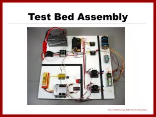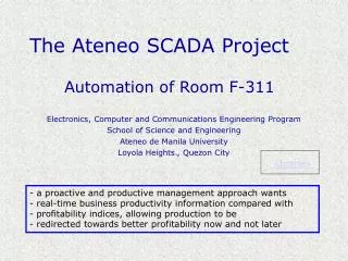
SCADA Test Bed Project
SCADA Test Bed Project. Alaap Anujan, Mike Beacham , Chris Dyer Sponsor: Dr. Brian Johnson. ORIGINAL PROJECT OBJECTIVES. Display real time system status and alarms on a user accessible HMI screen Critical alarms to be sent out as text/email messages Maintenance access to connected devices.

SCADA Test Bed Project
E N D
Presentation Transcript
SCADA Test Bed Project Alaap Anujan, Mike Beacham, Chris Dyer Sponsor: Dr. Brian Johnson
ORIGINAL PROJECT OBJECTIVES Display real time system status and alarms on a user accessible HMI screen Critical alarms to be sent out as text/email messages Maintenance access to connected devices
PROBLEMS WE EXPECTED TO ENCOUNTER • Compatibility issues with older technology • Security concerns with network connectivity • Programming the existing test bed to suit the project requirements
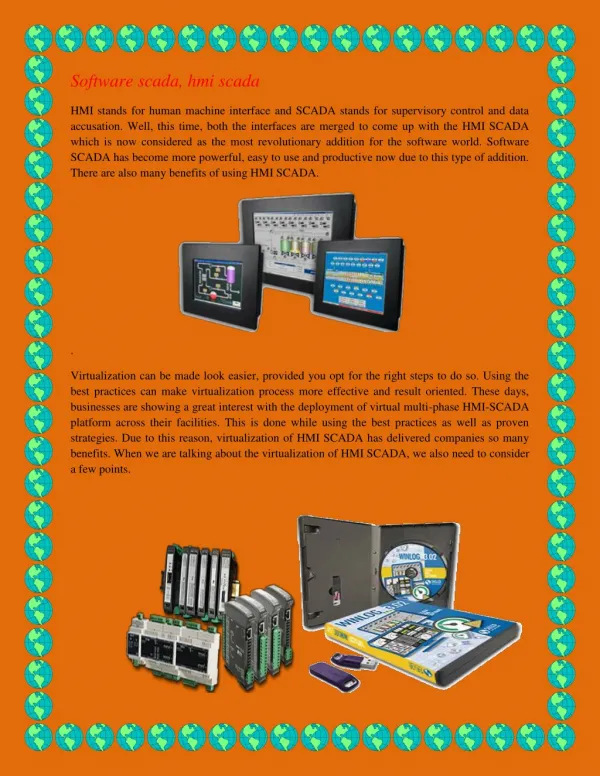
SYSTEM COMPONENTS SEL 2030 RTU Six SEL-734 Meters Synchronizing clock Alarms for motion and temperature SEL 3530 RTAC (Room for future expansion) Computer on Idaho Network (for access)
SEL-2030 RTU Data Concentrator Self contained network switch Capable of passing time synchronization Automation logic platform Can record faults/alarms
PROJECT IMPLEMENTATION Step 1: Assessing the existing SCADA Test Bed Setup Step 2: Tracing and updating the wiring Step 3: Determine NEW system architecture Step 4: Locate proper software tools. Step 5: Project Implementation
PROJECT IMPLEMENTATION (PART II) • Using SEL 5020, update RTU configuration to current status • Update port inputs to attached 724’s • Reprogram RTU to accept changes • Wire alarm outputs to RTU inputs • Incorporate RTAC into system • Connect RTU to RTAC via serial RS232 • Develop HMI tags onto RTAC software • Implement alarm messages into mailer server • Used IEC 61131 structured text format • Used SMTP router to use mailer daemon • Got help from PK Northcutt
The HMI (Human Machine Interface) • Displays the current state of the system and operational alarms on a user friendly interface. • Model Power System metering data • Device & system status • Can be viewed from a remote location. • https://129.101.221.82/default.sel • Configurable for read only for security purposes • Can be modified for future updates.
Opportunities, not problems! XP security updates stopping Test Bed isolated, and also disassembled. No real wiring guide Lacking proper software IT difficulties RTU improperly configured