
Spanning Tree Protocol
E N D
Presentation Transcript
Spanning Tree Protocol Semester 3, Ch. 5 Sandra Coleman, CCNA, CCAI
Redundancy • Five 9’s uptime = 99.999% uptime, this equates to only 5.25 minutes of downtime per year! • Requires reliability…which is achieved by reliable equipment and fault tolerant networks • Redundant topologies – • Goal - eliminate network outages caused by a single point of failure.
If the bridge is flooded or damaged by an accident, travel to the town center across the bridge is impossible. A second bridge across the river creates a redundant topology. The suburb is not cut off from the town center if one bridge is impassable
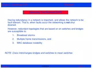
Redundant Switched Topologies • Eliminates single points of failure • Switches flood frames for unknown destinations until they learn their MAC addresses • Broadcasts/Multicasts are flooded out all ports EXCEPT the one on which it was received • Can cause the following problems: • broadcast storms • multiple Ethernet frame copies • MAC address table instability problems
Redundant Switched Topology • When multiple paths exist between two devices on the network and STP has been disabled on those switches, a Layer 2 loop can occur. If STP is enabled on these switches, which is the default, a Layer 2 loop would not occur.
Broadcast Storms • Defined - A state in which a message that has been broadcast across a network results in even more responses, and each response results in still more responses in a snowball effect • Caused by continued sending of broadcasts or multicasts over and over. • Will continue until one of the switches is disconnected. • Switches get so busy with the broadcasts, they can’t forward normal user traffic which causes it to seem as if the network is down or extremely slow.
Multiple Frame Transmissions • Occurs when multiple devices are seeking to retrieve information from another device. • A single devices might be seeking a MAC address of a particular host. • In seeking the address, the request travels through other networking devices which also begin seeking the MAC address.
Multiple frame transmissions • In a redundant switched network it is possible for an end device to receive multiple frames. • Assume that the MAC address of Router Y has been timed out by both switches. • Also assume that Host X still has the MAC address of Router Y in its ARP cache and sends a unicast frame to Router Y.
Multiple frame transmissions • The router receives the frame because it is on the same segment as Host X. • Switch A does not have the MAC address of the Router Y and will therefore flood the frame out its ports. (Segment 2) • Switch B also does not know which port Router Y is on. • Note: Switch B will forward the the unicast onto Segment 2, creating multiple frames on that segment. • After Switch B receives the frame from Switch A , it then floods the frame it received causing Router Y to receive multiple copies of the same frame. • This is a causes of unnecessary processing in all devices.
Media access control -database instability • In a redundant switched network it is possible for switches to learn the wrong information. • A switch can incorrectly learn that a MAC address is on one port, when it is actually on a different port. • Host X sends a frame directed to Router Y. • Switches A and B learn the MAC address of Host X on port 0. • The frame to Router Y is flooded on port 1 of both switches. • Switches A and B see this information on port 1 and incorrectly learn the MAC address of Host X on port 1.
Redundant topology & spanning tree • No TTL field in Layer 2 Ethernet header(as there is in IP headers). Therefore is a frame is caught in a loop, it can loop forever, wasting bandwidth • Switching loops are necessary for reliability, but networks cannot have loops. ???? • Solution: allow physical loops, but create a loop-free logical topology.
Spanning Tree Protocol • Loop free switched topology • Usually star or extended star logical topology • SPANNING means all devices are reachable or spanned • Spanning tree algorithm is used to create this topology. Can take a relatively long time to converge • Rapid spanning-tree algorithm is being introduced to reduce the time it takes to compute a loop free logical topology • STP ensures that there is only one logical path between all destinations on the network by intentionally blocking redundant paths that could cause a loop (loop-free path).
Spanning Tree Protocol • IEEE 802.1D – allows the use of ST algorithm to construct a loop free shortest path network • Shortest path is based on cumulative link costs • Establish a root node called the root bridge • Establish one path for reaching every node…originating from the root bridge. • Links not part of the shortest path are blocked • Features that contribute to the time it takes for total convergence: • Max-age timer • Listening forward delay • Learning forward delay
Spanning Tree Protocol • Data frames received on blocked links are dropped • Links that will cause bridging loops are blocked • BPDU – Bridge Protocol Data Unit • Allows the formation of the loop free topology • BPDUs continue to be received on blocked ports. If an active path fails, a new one can be calculated
BPDUs • Contain enough info that all switches can: • Select a single switch that will act as the root of the spanning tree • Calculate the shortest path from itself to the root switch • Designate one of the switches as the closest one to the root, for each LAN segment. This bridge is called the “designated switch”. • Choose one of its ports as its root port, for each non-root switch. This is the interface that gives the best path to the root switch. • Select ports that will forward frames and are part of the spanning tree, the designated ports. • Non-designated ports are blocked
Spanning tree operation • Should be one spanning tree per network • For every converged switched network, the following elements exist: • One root bridge per network • One root port per non root bridge • One designated port per segment • These forward data traffic • Unused, non-designated ports • These discard data traffic
Two Key Concepts: BID and Path Cost • STP executes an algorithm called Spanning Tree Algorithm (STA). • STA chooses a reference point, called a root bridge, and then determines the available paths to that reference point. • If more than two paths exists, STA picks the best path and blocks the rest • STP calculations make extensive use of two key concepts in creating a loop-free topology: • Bridge ID • Path Cost
Bridge ID (BID) • Bridge ID (BID) is used to identify each bridge/switch. • The BID is used in determining the center of the network, in respect to STP, known as the root bridge. • Consists of two components: • A 2-byte Bridge Priority: Cisco switch defaults to 32,768 or 0x8000. • A 6-byte MAC address
Bridge ID (BID) • Bridge Priority is usually expressed in decimal format and the MAC address in the BID is usually expressed in hexadecimal format. • BID is used to elect a root bridge • Lowest Bridge ID is the root. • If all devices have the same priority, the bridge with the lowest MAC address becomes the root bridge. (Yikes!)
Path Cost • Bridges use the concept of cost to evaluate how close they are to other bridges. • This will be used in the STP development of a loop-free topology . • Originally, 802.1d defined cost as 1000/bandwidth of the link in Mbps. • Cost of 10Mbps link = 100 or 1000/10 • Cost of 100Mbps link = 10 or 1000/100 • Cost of 1Gbps link = 1 or 1000/1000 • Running out of room for faster switches including 10 Gbps Ethernet. • 10-Gb/s Ethernet ports have a port cost of 2, • 1-Gb/s Ethernet ports have a port cost of 4, • 100-Mb/s Fast Ethernet ports have a port cost of 19 • 10-Mb/s Ethernet ports have a port cost of 100.
Path Cost • Path cost is the sum of all the port costs along the path to the root bridge. • The paths with the lowest path cost become the preferred path, and all other redundant paths are blocked.
Path Cost • You can modify the path cost by modifying the cost of a port. • Exercise caution when you do this! • BID and Path Cost are used to develop a loop-free topology . • But first the Four-Step STP Decision Sequence
Four-Step STP Decision Sequence • When creating a loop-free topology, STP always uses the same four-step decision sequence: Four-Step decision Sequence Step 1 - Lowest BID Step 2 - Lowest Path Cost to Root Bridge Step 3 - Lowest Sender BID Step 4 - Lowest Port ID
BID Fields • The BID is used to determine the root bridge on a network. • The BID field of a BPDU frame contains 3 separate fields. • Each field is used during the root bridge election. 1. Bridge Priority • The bridge priority is a customizable value that you can use to influence which switch becomes the root bridge. • The switch with the lowest priority, which means lowest BID, becomes the root bridge (the lower the priority value, the higher the priority). • The default value for the priority of all Cisco switches is 32768. The priority range is between 1 and 65536; 1 is the highest priority. 2. Extended System ID • The early STP was designed for networks that did not use VLANs. • When VLANs started became common, the extended system ID field contains the ID of the VLAN with which the BPDU is associated. • The bridge priority values can only be multiples of 4096. • The extended system ID is added to identify the priority and VLAN of BPDU. 3. MAC Address • When two switches are configured with the same priority and have the same extended system ID (default setting), the switch with the MAC address with the lowest hexadecimal value has the lower BID. • It is recommended to configure the desired root bridge switch with a lower priority to ensure that it is elected root bridge.
Four-Step STP Decision Sequence BPDU key concepts: • Bridges save a copy of only the best BPDU seen on every port. • At startup, each switch initially assumes that it is the root bridge, so the BPDU frames that are sent, contain the BID of the local switch as the root ID. • When making this evaluation, it considers all of the BPDUs received on the port, as well as the BPDU that would be sent on that port. • As every BPDU arrives, it is checked against this four-step sequence to see if it is more attractive (lower in value) than the existing BPDU saved for that port. • Only the lowest value BPDU is saved. • Bridges send configuration BPDUs until a more attractive BPDU is received. • Okay, lets see how this is used...
Three Steps of Initial STP Convergence • The STP algorithm uses three simple steps to converge on a loop-free topology. • Switches go through three steps for their initial convergence: STP ConvergenceStep 1 Elect one Root BridgeStep 2 Elect Root PortsStep 3 Elect Designated Ports root bridge
Three Steps of Initial STP Convergence STP Convergence Step 1 Elect one Root Bridge Step 2 Elect Root Ports Step 3 Elect Designated Ports
Step 1 - Elect one Root Bridge • Each switch in the broadcast domain initially assumes that it is the root bridge for the spanning-tree instance, so the BPDU frames sent contain the BID of the local switch as the root ID. • Each switch maintains local information about its own BID, the root ID, and the path cost to the root. • By default, BPDU frames are sent every 2 seconds. • When adjacent switches receive a BPDU frame, they compare the root ID from the BPDU frame with the local root ID. • If the root ID in the BPDU is lower than the local root ID, the switch updates the local root ID and the ID in its BPDU messages. • These messages serve to indicate the new root bridge on the network. • Also, the path cost is updated to indicate how far away the root bridge is. (looking for the shortest path to the root bridge) • For example, a Fast Ethernet switch port, the path cost would be set to 19. • If the local root ID is lower than the root ID received in the BPDU frame, the BPDU frame is discarded.
Elect the root bridge • After a root ID has been updated to identify a new root bridge, all subsequent BPDU frames sent from that switch contain the new root ID and updated path cost. • Use to determine which ports will forward frames as part of the spanning tree. • As the BPDU frames pass between other adjacent switches, the path cost is continually updated to indicate the total path cost to the root bridge. • Each switch in the spanning tree uses its path costs to identify the best possible path to the root bridge.
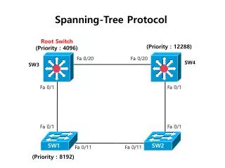
Step 1 Elect one Root Bridge Cat-A has the lowest Bridge MAC Address, so it wins the Root War! All 3 switches have the same default Bridge Priority value of 32,768
Step 1 Elect one Root Bridge • At the beginning, all bridges assume they are the center of the universe and declare themselves as the Root Bridge, by placing its own BID in the Root BID field of the BPDU. • Once all of the switches see that Cat-A has the lowest BID, they are all in agreement that Cat-A is the Root Bridge. • Can be influenced by network admin by setting switch priority to a smaller value than the default. Do this cautiously!
Configure and Verify the BID • There are 2 methods used to configure bridge priority value. • Method 1 • To ensure the switch has the lowest priority value, use the spanning-tree vlanvlan-id root primary in global configuration. • The priority for the switch is set to the predefined value of 24576 or to the next 4096 increment value below the lowest bridge priority detected on the network. • If an alternate root bridge is desired, use the spanning-tree vlanvlan-id root secondary global configuration mode. • It sets the priority for the switch to the predefined value of 28672. • This ensures that this switch becomes the root bridge if the primary root bridge fails and the rest of the switches in the network have the default 32768 priority value defined. • Method 2 • Another method for configuring the bridge priority value is using the spanning-tree vlanvlan-id priority value global configuration mode command. • This command gives you more granular control over the bridge priority value. • The priority value is configured in increments of 4096 between 0 and 65536. • To verify the bridge priority of a switch, use the show spanning-tree privileged EXEC mode command. • In the example, the priority of the switch has been set to 24576. Also notice that the switch is designated as the root bridge for the spanning-tree instance. 24576 24576 20480 28672
Port Roles • There are 4 port roles that switch automatically configured for SPT process. 1. Root Port - Root port exists on non-root bridges and it is the port with the best path to the root bridge. • Only one root port is allowed per bridge. • S2 and S3 have root ports on the trunk links connecting back to S1. 2. Designated Port - The designated port exists on root and non-root bridges. • For root bridges, all switch ports are designated ports. • For non-root bridges, a designated port is the switch port that receives and forwards frames toward the root bridge as needed. • Only one designated port is allowed per segment. • S1 has both sets of ports for its 2 trunk links configured as designated ports. S2 also has a designated port configured on the trunk link going toward S3. 3. Non-designated Port - The non-designated port is a switch port that is blocked, so it is not forwarding data frames and not populating the MAC address table with source addresses. • Decisions on which port to block if they have equal costs depend on the port priority and identity. • A non-designated port is not a root port or a designated port. • For some variants of STP, the non-designated port is called an alternate port. • S3 has the only non-designated ports in the topology. • The non-designated ports prevent the loop from occurring. 4. Disabled Port - The disabled port is a switch port that is administratively shut down. • A disabled port does not function in the spanning-tree process. • There are no disabled ports in the example.
Three Steps of Initial STP Convergence STP Convergence Step 1 Elect one Root Bridge Step 2 Elect Root Ports Step 3 Elect Designated Ports
Step 2 Elect Root Ports • Now that the Root War has been won, switches move on to selecting Root Ports. • A bridge’s Root Port is the port closest to the Root Bridge. • Bridges use the cost to determine closeness. • Every non-Root Bridge will select one Root Port! • Specifically, bridges track the Root Path Cost, the cumulative cost of all links to the Root Bridge.
Step 2 Elect Root Ports BPDU Cost=0 BPDU Cost=0 BPDU Cost=0+19=19 BPDU Cost=0+19=19 Step 1 • Cat-A sends out BPDUs, containing a Root Path Cost of 0. • Cat-B receives these BPDUs and adds the Path Cost of Port 1/1 to the Root Path Cost contained in the BPDU. Step 2 • Cat-B adds Root Path Cost 0 PLUS its Port 1/1 cost of 19 = 19
Step 2 Elect Root Ports BPDU Cost=0 BPDU Cost=0 BPDU Cost=19 BPDU Cost=19 Step 3 • Cat-B uses this value of 19 internally and sends BPDUs with a Root Path Cost of 19 out Port 1/2. Step 4 • Cat-C receives the BPDU from Cat-B, and increased the Root Path Cost to 38 (19+19). (Same with Cat-C sending to Cat-B.) BPDU Cost=19 BPDU Cost=19 BPDU Cost=38 (19+19) BPDU Cost=38 (19+19)
Step 2 Elect Root Ports BPDU Cost=0 BPDU Cost=0 BPDU Cost=19 BPDU Cost=19 Step 5 • Cat-B calculates that it can reach the Root Bridge at a cost of 19 via Port 1/1 as opposed to a cost of 38 via Port 1/2. • Port 1/1 becomes the Root Port for Cat-B, the port closest to the Root Bridge. • Cat-C goes through a similar calculation. Note: Both Cat-B:1/2 and Cat-C:1/2 save the best BPDU of 19 (its own). Root Port Root Port BPDU Cost=38 (19+19) BPDU Cost=38 (19+19)
Elect Root Ports • Every switch in a spanning-tree topology, except for the root bridge, has a single root port defined. • The root port is the switch port with the lowest path cost to the root bridge. • Normally path cost alone determines which switch port becomes the root port. • Switch ports with equivalent path costs to the root use the configurable port priority value. • They use the port ID to break a tie. • When a switch chooses one equal path cost port as a root port over another, the losing port is configured as the non-designated to avoid a loop.
Three Steps of Initial STP Convergence STP Convergence Step 1 Elect one Root Bridge Step 2 Elect Root Ports Step 3 Elect Designated Ports
Step 3 Elect Designated Ports • The loop prevention part of STP becomes evident during this step, electing designated ports. • A Designated Port functions as the single bridge port that both sends and receives traffic to and from that segment and the Root Bridge. • Each segment in a bridged network has one Designated Port, chosen based on cumulative Root Path Cost to the Root Bridge. • The switch containing the Designated Port is referred to as the Designated Bridge for that segment. • To locate Designated Ports, lets take a look at each segment. • Root Path Cost, the cumulative cost of all links to the Root Bridge.
Root Path Cost = 0 Root Path Cost = 0 Segment 1 Segment 2 Step 3 Elect Designated Ports • Segment 1: Cat-A:1/1 has a Root Path Cost = 0 (after all it has the Root Bridge) and Cat-B:1/1 has a Root Path Cost = 19. • Segment 2: Cat-A:1/2 has a Root Path Cost = 0 (after all it has the Root Bridge) and Cat-C:1/1 has a Root Path Cost = 19. • Segment 3: Cat-B:1/2 has a Root Path Cost = 19 and Cat-C:1/2 has a Root Path Cost = 19. It’s a tie! Root Path Cost = 19 Root Path Cost = 19 Root Port Root Port Root Path Cost = 19 Root Path Cost = 19 Segment 3
Root Path Cost = 0 Root Path Cost = 0 Segment 1 Segment 2 Step 3 Elect Designated Ports Designated Port Designated Port Segment 1 • Because Cat-A:1/1 has the lower Root Path Cost it becomes the Designate Port for Segment 1. Segment 2 • Because Cat-A:1/2 has the lower Root Path Cost it becomes the Designate Port for Segment 2. Root Path Cost = 19 Root Path Cost = 19 Root Port Root Port Root Path Cost = 19 Root Path Cost = 19 Segment 3
Root Path Cost = 0 Root Path Cost = 0 Segment 1 Segment 2 Designated Port Designated Port Segment 3 • Both Cat-B and Cat-C have a Root Path Cost of 19, a tie! • When faced with a tie (or any other determination) STP always uses the four-step decision process: 1. Lowest Root BID; 2. Lowest Path Cost to Root Bridge; 3. Lowest Sender BID; 4. Lowest Port ID Root Path Cost = 19 Root Path Cost = 19 Root Port Root Port Root Path Cost = 19 Root Path Cost = 19 Segment 3
Root Path Cost = 0 Root Path Cost = 0 Segment 1 Segment 2 Designated Port Designated Port Segment 3 (continued) • 1) All three switches agree that Cat-A is the Root Bridge, so this is a tie. • 2) Root Path Cost for both is 19, also a tie. • 3) The sender’s BID is lower on Cat-B, than Cat-C, so Cat-B:1/2 becomes the Designated Port for Segment 3. • Cat-C:1/2 therefore becomes the non-Designated Port for Segment 3. Root Path Cost = 19 Root Path Cost = 19 Root Port Root Port 32,768.CC-CC-CC-CC-CC-CC 32,768.BB-BB-BB-BB-BB-BB Root Path Cost = 19 Root Path Cost = 19 Designated Port Segment 3 Non-Designated Port
Non-designated ports • When two switches are connected to the same LAN segment, and root ports have already been defined, the two switches have to decide which port gets to be configured as a designated port and which one is left as the non-designated port. • Generally, the switch with the lower BID has its port configured as a designated port, • while the switch with the higher BID has its port configured as a non-designated port. • However, keep in mind that the first priority is the lowest path cost to the root bridge and that only if the port costs are equal, is the BID of the sender. • As a result, each switch determines which port roles are assigned to each of its ports to create the loop-free spanning tree.
Spanning Tree Port States • Blocking (20 secs) • Is this a root bridge or a designated port • Can only receive BPDUs Data frames are discarded • Listening (15 secs) • Determine if there are other paths to the root bridge • All paths, except lowest cost, go back to blocking • Learning (15 secs) • Learning MAC addresses from any traffic, does not forward user data • Forwarding • User data is forwarded, BPDUs are processed, and MAC addresses are learned • Disabled – the layer 2 port does NOT participate in STP and doesn’t forward frames.
STP Recalculation – Topology Changes • Convergence occurs when all the switch and bridge ports are in either the forwarding or blocked state • Network changes require the switches to recompute the Spanning Tree and therefore recalculate. This disrupts user traffic. • Can take up to 50 seconds to go from blocking state to forwarding state with 802.1D standards. • The entire process of electing the root bridge, determining the root ports, and determining the designated and non-designated ports happens within the 20-second blocking port state.
BPDU Timers • The amount of time that a port stays in the various port states depends on the BPDU timers. • Only the switch in the role of root bridge may send information through the tree to adjust the timers. These contribute to the time it takes for the network to fully converge! • Hello time (2 seconds) • Forward delay (15 seconds) • Maximum age (20 seconds) • At power up: Every switch port goes through the blocking, listening and learning states. The ports then stabilize to the forwarding or blocking state. • During a topology change: A port temporarily implements the listening and learning states for a specified period called the "forward delay interval.“ • They must also allow the frame lifetime to expire for frames that have been forwarded using the old topology