Download
1 / 61
1.09k likes | 2.11k Views
ENG2000 Chapter 10 Optical Properties of Materials. Overview. The study of the optical properties of materials is a huge field and we will only be able to touch on some of the most basic parts

E N D
Overview • The study of the optical properties of materials is a huge field and we will only be able to touch on some of the most basic parts • So we will consider the essential properties such as absorption/reflection/transmission and refraction • Then we will look at other phenomena like luminescence and fluorescence • Finally we will mention applications, in particular optical fibres and lasers
Nature of light • Light is an electromagnetic wave: • with a velocity given by c = 1/(00) = 3 x 10⁸ m/s • In view of this, it is not surprising that the electric field component of the wave should interact with electrons electrostatically http://www.astronomynotes.com/light/emanim.gif
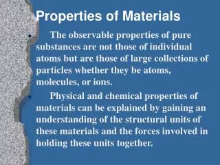
Many of the electronic properties of materials, information on the bonding, material composition etc. was discovered using spectroscopy, the study of absorbed or emitted radiation • evidence for energy levels in atoms • evidence for energy bands and band-gaps • photoelectric effect
General description of absorption • Because of conservation of energy, we can say that I0 = IT + IA + IR • Io is the intensity (W/m2) of incident light and subscripts refer to transmitted, absorbed or reflected • Alternatively T + A + R = 1 where T, A, and R are fractions of the amount of incident light • T = IT/I0, etc. • So materials are broadly classed as • transparent:relatively little absorption and reflection • translucent:light scattered within the material (see right) • opaque:relatively little transmission http://www.tekano.pwp.blueyonder.co.uk/tekano/translucent.jpg
If the material is not perfectly transparent, the intensity decreases exponentially with distance • Consider a small thickness of material, x • The fall of intensity in x is I so I = -a.x.I • where is the absorption coefficient (dimensions are m-1) • In the limit of x 0, we get • The solution of which is I = I0 exp(–x) • Taking “ln” of both sides, we have: • which is known as Lambert’s Law (he also has a unit of light intensity named for him)
Thus, if we can plot -ln(I) against x, we should find from the gradient • Depending on the material and the wavelength, light can be absorbed by • nuclei – all materials • electrons – metals and small band-gap materials
ATOMIC ABSORPTION • How the solid absorbs the radiation depends on what it is! • Solids which bond ionically, show high absorption because ions of opposite charge move in opposite directions • in the same electric field • hence we get effectively twice the interaction between the light and the atoms • Generally, we would expect absorption mainly in the infrared • because these frequencies match the thermal vibrations of the atoms
If we think of our atom-on-springs model, there is a single resonance peak: • But things are more complex when the atoms are connected – phonons • recall transverse and longitudinal optical phonons absorption f f0
Electronic absorption • Absorption or emission due to excitation or relaxation of the electrons in the atoms http://www.nhn.ou.edu/~kieran/reuhome/vizqm/figs/hydrogen.gif
Molecular materials • Materials such as organic (carbon containing) solids or water consist of molecules which are relatively weakly connected to other molecules • Hence, the absorption spectrum is dominated by absorptions due to the molecules themselves • e.g. water molecule: http://www.sbu.ac.uk/water/images/molecul5.jpg
The spectrum of liquid water http://www.sbu.ac.uk/water/images/watopt.jpg
Since the bonds have different “spring constants”, the frequencies of the modes are different • when the incident illumination is of a wavelength that excites one of these modes, the illumination is preferentially absorbed • This technique allows us to measure concentrations of different gas species in, for example, the atmosphere • by fitting spectra of known gases to the measured atmospheric spectra, we can figure out the quantities of each of the gases
Optical properties of metals • Recall that the energy diagram of a metal looks like: • EF is the energy below which, at 0K, all electron states are full and above which they are empty • this is the Fermi Energy • For T > 0, EF is the energy at which half of the available energy states are occupied • Semiconductors also have a Fermi level • for an intrinsic material EF is in the middle of the bandgap • nearer Ec for n-type; nearer Ev for p-type emptylevels T = 0K EF full levels
This structure for metals means that almost any frequency of light can be absorbed • Since there is a very high concentration of electrons, practically all the light is absorbed within about 0.1µm of the surface • Metal films thinner than this will transmit light • e.g. gold coatings on space suit helmets • Penetration depths (I/I0 = 1/e) for some materials are: • water: 32 cm • glass: 29 cm • graphite: 0.6 µm • gold: 0.15µm
So what happens to the excited atoms in the surface layers of metal atoms? • they relax again, emitting a photon • The energy lost by the descending electron is the same as the one originally incident • So the metal reflects the light very well – about 95% for most metals • metals are both opaque and reflective • the remaining energy is usually lost as heat • In terms of electrostatics, the field of the radiation causes the free electrons to move and a moving charge emits electromagnetic radiation • hence the wave is re-emitted = reflected
The metal appears “silvery” since it acts as a perfect mirror • OK then, why are gold and copper not silvery? • because the band structure of a real metal is not always as simple as we have assumed • there can be some empty levels below EF and the energy re-emitted from these absorptions is not in the visible spectrum • Metals are more transparent to very high energy radiation (x- & - rays) when the inertia of the electrons themselves is the limiting factor
aluminum spectrum is relatively flat gold reflects lots of red wavelengths red blue • Reflection spectra for gold and aluminum are: http://www.thermo.com/eThermo/CMA/Images/Various/109Image_12275.gif
EC EG EV hole Electronic absorption in non-metals • Dielectrics and semiconductors behave essentially the same way, the only difference being in the size of the bandgap • We know that photons with energies greater than Eg will be absorbed by giving their energy to electron-hole pairs • which may or may not re-emit light when they relax
Hence, the absorption coefficients of various semiconductors look like:
EC phonon hf1 hf2 EV • Semiconductors can appear “metallic” if visible photons are all reflected (like Ge) but those with smaller Eg, such as CdS look coloured • yellow for CdS which absorbs 540nm and above • The above picture is good for pure materials but impurities can add extra absorption features
Impurity levels divide up the bandgap to allow transitions with energies less than Eg • Recombination can be either radiative (photon) or non-radiative (phonon) depending on the transition probabilities • Practical p-n diodes usually contain a small amount of impurity to help recombination because Si has a relatively low recombination “efficiency” • for the same reason that Si is inefficient at generating light
Refraction in non-metals • One of the most important optical properties of non-metallic materials is refraction • This refers to the bending of a light beam as it passes from one material into another • e.g. from air to glass • We define the index of refraction to be n = c/v • where c is the speed of light in a vacuum and v is the speed of light in the material (which is in general wavelength-dependent) • A familiar example is the prism where the different amounts of bending separates out the wavelengths
Refraction is also vital for other applications, such as: • optical fibres – keeps the light in • semiconductor laser – keeps the light in the amplifying cavity of the laser • Given that • where µ and µ0 (= µrµ0) are the permeability of the material and free space, respectively (a magnetic property) • and e and e0 (= ere0) are the permittivity of the material and free space, respectively (an electrostatic property) • We find that n = √(µrer) (≈ √er for many materials)
Since light is an electromagnetic wave, the connection with both the dielectric permittivity () and the magnetic permeability (µ) is not surprising • The index of refraction is therefore a consequence of electrical polarization, especially electronic polarization • Hence, the radiation loses energy to the electrons – +
Since E = hv/, and doesn’t change, the velocity must be smaller in the material than in free space • since we lose E to the atoms, v must also decrease • Electronic polarization tends to be easier for larger atoms so n is higher in those materials • e.g. glass: n ~ 1.5 • lead crystal: n ~ 2.1 (which makes glasses and chandeliers more sparkly!) • n can be anisotropic for crystals which have non-cubic lattices
Reflection in non-metals • Reflection occurs at the interface between two materials and is therefore related to index of refraction • Reflectivity, R = IR/I0, where the I’s are intensities • Assuming the light is normally incident to the interface: • where n1 and n2 are the indices for the two materials • Optical lenses are frequently coated with antireflection layers such as MgF2 which work by reducing the overall reflectivity • some lenses have multiple coatings for different wavelengths n2 n1
Spectra • So we have seen that reflection and absorption are dependent on wavelength • and transmission is what’s left over! • Thus the three components for a green glass are: Callister Fig. 21.8
Colours • Small differences in composition can lead to large differences in appearance • For example, high-purity single-crystal Al2O3 is colourless • sapphire • If we add only 0.5 - 2.0% of Cr2O3 we find that the material looks red • ruby • The Cr substitutes for the Al and introduces impurity levels in the bandgap of the sapphire • These levels give strong absorptions at: • 400nm (green) and 600nm (blue) • leaving only red to be transmitted
The spectra for ruby and sapphire look like: • A similar technique is used to colour glasses or pottery glaze by adding impurities into the molten state: • Cu2+: blue-green, Cr3+: green • Co2+: blue-violet, Mn2+: yellow http://www.valleydesign.com/images/sapp.jpg http://home.achilles.net/~jtalbot/glossary/photopumping.gif
Translucency • Even after the light has entered the material, it might yet be reflected out again due to scattering inside the material • Even the transmitted light can lose information by being scattered internally • so a beam of light will spread out or an image will become blurred • In extreme cases, the material could become opaque due to excessive internal scattering • Scattering can come from obvious causes: • grain boundaries in poly-crystalline materials • fine pores in ceramics • different phases of materials
In highly pure materials, scattering still occurs and an important contribution comes from Rayleigh scattering • This is due to small, random differences in refractive index from place to place • In amorphous materials such as glass this is typically due to density or compositional differences in the random structure • In crystals, lattice defects, thermal motion of atoms etc. also give rise to Rayleigh scattering
Rayleigh scattering also causes the sky to be blue. The reason for this is the wavelength-dependence of Rayleigh scattering • scattering goes as l-4 • so since lred ~ 2lblue blue light is scattered ~16 times more than red light • This mechanism is of great technological importance because it governs losses in optical fibres for communication • But before we get onto fibres, we will mention a couple more basic effects
Dispersion • Dispersion is a general name given to things which vary with wavelength • For example, the wavelength-dependence of the index of refraction is termed the dispersion of the index • Another important case arises because the speed of the wave depends on its wavelength • If a pulse of white light is transmitted through a material, different wavelengths arrive at the other end at different times • this is also called dispersion
Luminescence • Luminescence is the general term which describes the re-emission of previously absorbed radiative energy • Common types are photo- , electro-, and cathodo-luminescence, depending on whether the original incident radiation was • light of a different wavelength – e.g. fluorescent light • electric field – e.g. LED • electrons – e.g. electron gun in a cathode ray tube (CRT) • There is also chemo-luminescence due to chemical reactions which make the glowing rings seen at fairgrounds!
E2 flip phosp. fluor. E3 incident phosp. flip E1 • Luminescence is further divided into phosphorescence and fluorescence • Fluorescence and phosphorescence are distinguished by the electron transitions requiring no change or a change of spin, respectively • hence fluorescence is a faster process because no change of spin is required, around 10-5 – 10-6s • phosphorescence takes about 10-4 – 101s • Thus the energy diagram might be like:
If the energy levels are actually a range of energies, then: • So the light emitted by fluorescence is of longer wavelength than the incident light • since the energy is smaller • and phosphorescent light is typically longer wavelength than fluorescent light phonon emission~10-12s per hop fluorescence, ~10-5s
In fluorescent lights, the plasma generates UV light, and a fluorescent coating on the walls of the tube converts this to visible light • these lights have a visible flicker because (60Hz)-1 > 10-5s • Rather confusingly, materials that do this are generally called phosphors • To obtain a white light, a mixture of phosphors must be used, each fluorescing at a different wavelength • TV tubes usually use materials doped with different elements to give the colours: • ZnS doped with Cu+ gives green • ZnS:Ag gives blue • YVO4:Eu gives red
Optical fibres • Fibre-optic technology has revolutionised telecommunications owing to the speed of data transmission: • equivalent to >3 hrs of TV per second • 24,000 simultaneous phone calls • 0.1kg of fibre carries same information as 30,000kg of copper cable • Owing to attenuation in the cable, transmission is usually digital and the system requires several sections: optical optical encoder conversion to optical repeater detection decoder http://www.ngflscotland.gov.uk/connected/connected5/images/fibreoptic.jpg
Obviously, the loss in the cable is important because is determines the maximum uninterrupted length of the fibre • We know that losses depend on the wavelength of the light and the purity of the material • recall the penetration depth for glass was ~30cm • In 1970, 1km of fibre attenuated 850nm light by a factor of 100 • By 1979, 1km of fibre attenuated 1.2µm light by a factor of only 1.2 • this light is infrared • Now, over 10km of optical fibre silica glass, the loss is the same as 25mm of ordinary window glass!
For such high-purity materials, Rayleigh scattering is the dominant loss mechanism: water
The Rayleigh scattering results from minute local density variations which are present in the liquid glass due to Brownian motion and become frozen into the solid • The really clever part about optical fibres is that the light is guided around bends in the fibre • This is achieved by total internal reflection at the boundary of the fibre
Thus, the cross section of the fibre is designed as follows http://www.datacottage.com/nch/images/fibreconstruct.gif
n • The light is transmitted in the core and total internal reflection is made possible by the difference in the index of refraction between the cladding and the core • A simple approach is the “step-index” design: • The main problem with this design is that different light rays follow slightly different trajectories
So different light rays from an input pulse will take slightly different paths and will therefore reach the output at different times • Hence the input pulse is found to broaden during transmission: • This limits the data rate of digital communication signal signal t t in out
n • Such broadening is largely eliminated by using a “graded-index” design: • This is achieved by doping the silica with B2O3 or GeO2 parabolically as shown above • Now, waves which travel in the outer regions, do so in a lower refractive index material • and their velocity is higher (v = c/n)
Therefore, they travel both further and faster • as a result, they arrive at the output at almost the same time as the waves with shorter trajectories • Anything that might cause scattering in the core must be minimised • Cu, Fe, V are all reduced to parts per billion • H2O and OH concentrations also need to be very low • Variations in the diameter of the fibre also cause scattering • this variation is now <1µm over a length of 1km • To avoid dispersion of different wavelengths, lasers are used as the light sources • many data channels are possible using wavelength division multiplexing (WDM)
A convenient fact is that compound semiconductor lasers can emit IR light close to the 1.55µm wavelength where the fibre absorbs least • Referring back to the system diagram, it would be advantageous to integrate the encoder and transmitter • so the circuits and the light emitter can be integrated • This is why there is so much interest in getting light out of porous silicon or Si compounds • where thin strands of material exhibit quantum-mechanical effects which adjust the Si band structure to facilitate efficient light emission
http://ghuth.com/Porous%20silicon.jpg http://porous.silicon.online.fr/images/poreux.jpg