Download
1 / 60
600 likes | 636 Views
Explore basic properties, image quality, and recent developments in semiconductor detectors for medical imaging applications. Learn about energy resolution, semiconductor materials, and optimizing detector performance.

E N D
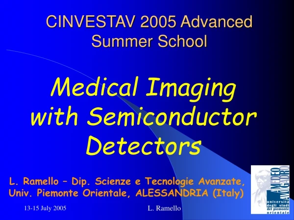
CINVESTAV 2005 Advanced Summer School Medical Imaging with Semiconductor Detectors L. Ramello – Dip. Scienze e Tecnologie Avanzate, Univ. Piemonte Orientale, ALESSANDRIA (Italy) L. Ramello
Topics • Basic properties of semiconductor detectors • Image quality: contrast, SNR, MTF, DQE • Recent detector developments: • MEDIPIX (2D pixels) • SYRMEP (Synchrotron Light Source) • High Z semiconductors • Dual Energy Mammography • Dual Energy Angiography L. Ramello
Basic properties of semiconductor detectors L. Ramello
Why semiconductor detectors ? Advantages for medical imaging with x-rays: High spatial resolution (down to ~50 micron) High detection efficiency, especially in the low energy range (mammography) Combine x-ray conversion and electrical signal generation Decrease radiation dose and/or improve image quality Semiconductor imaging system concepts: Digital radiography with scintillator + amorphous silicon (commercially available) Digital radiography with direct conversion in semiconductor material (R & D) PET and SPECT with high Z semiconductors (R & D) L. Ramello
Semiconductor materials • Atomic number Z, density and thickness probability of x-ray photon conversion • Average energy loss to create electron-hone pair, W (roughly proportional to Eg) energy resolution L. Ramello
Energy resolution Radiation ionization energy(W): determines the number of primary ionization events Band gap energy (Eg): lower value easier thermal generation of e-h pairs (kT = 26 meV for T = 300 K) L. Ramello
Semiconductor detectors • To fully exploit these attractive semiconductor detector features: • High electric field is needed to collect signal • Dedicated, low noise electronics is needed (usually the first element is a charge amplifier) • For silicon, a p-n junction is needed to reduce dark current (operation at room temperature is OK) • For germanium, cryogenic operation (liq. N2 temperature) is needed • Multichannel systems require special care for power density, connection technique, cross-talk L. Ramello
The p-n junction (1) Abrupt junction approximation Net charge density vs. distance Electric field vs. distance Electrostatic potential vs. distance Valence and Conduction band energies vs. distance L. Ramello
The p-n junction (2) • In reverse polarization (positive voltage to n-side): • the diode current density saturates at a low value Js • the depletion layer thickness (d) increases with increasing voltage, so does the active volume d = (2VB/eeND)1/2 e = ere0 12 e0 (Si) ND = donors/cm3 (n-Si) qV/kT = ratio between potential energy and thermal energy L. Ramello
The microstrip detector SIGNAL = number of electron-hole pairs: ne-h = DE/W, where W=3.62 eV for silicon • REVERSE POLARIZED DIODE • Depletion region => free from charge carriers: e-h pairs may be detected • Reverse Bias voltage (VB)=> controls diode depletion thickness, i.e. active volume • p-n junction capacitance per unit area C: • 1/C2 grows linearly with VB => • C-V measurement determines full depletion voltage VFD L. Ramello
A microstrip detector DC contact (to p+ implant) • AC coupling: Bias Line and resistors to bias each strip, without shorting adjacent strips • Guard ring(s) are essential to collect surface currents • This introduces a dead layer for edge-on geometry guard ring bias line first strip (AC contact) L. Ramello
A readout chain • This is just one possibility, the binary readout scheme – another one is to put an ADC instead of the discriminator, preserving the full analog information vthp IN OUT charge preamplifier vthn shaper discriminator calib in L. Ramello
The RX64 ASIC RX64 - Krakow UMM design - (28006500 m2)consists of: - 64 front-end channels (preamplifier, shaper, discriminator), - 64 pseudo-random counters (20-bit), - internal DACs: one 8-bit threshold setting and and two 5-bit for bias, - internal calibration circuit (square wave 1mV-30 mV), - control logic, - I/O circuit (interface to external bus). L. Ramello
Conversion efficiency (1) } 300 μm (standard thickness) } 10-20 mm μm (edge-on) Si (300 μm): efficiency drops to 50 % at 15 keV (Al window limits efficiency at low energies) Recover efficiency with edge-on orientation L. Ramello
Conversion efficiency (2) } 300 μm GaAs (Z ~32) } 10-20 mm μm Si (Z =14) GaAs (300 μm): efficiency drops to 50 % at 48 keV Material of choice for mammography, E ~ 22 keV L. Ramello
Image quality: contrast, SNR, MTF, DQE L. Ramello
X-ray beams (1) • X-rays are generated by bremsstrahlung of electrons emitted from cathode, accelerated by an applied voltage and impinging on the anode • The energy spectrum of x-rays is determined by: • Peak kilovoltage (kVp) • Anode material (concerning peaks at characteristic energies) • Intrinsec and added filtration Effect on an 80 kVp x-ray beam of added filtration with a light material (Al) and with a rare earth material (La, K-edge @ 39 keV) L. Ramello
X-ray beams (2) • Most common anode materials: • W (Z=74) for general radiographu (chest, whole body, …) • Mo (Z=42) & Rh (Z=45) for mammography • Cu (Z=29) for diffractometry • Energy emitted as x-rays is only 0.5-1% of input energy, the remaining part must be dissipated as heat • X-ray tubes with moderate power are with fixed anode, high power ones have a rotating anode to avoid melting • Typical currents are 1-5 mA for prolonged exposure (fluoroscopy) and 50-1000 mA for short exposures; exposure is measured in mAs L. Ramello
X-ray imaging techniques • Film: sensitivity is very low, it would require too high a dose to the patient • Film + screen: conventional radiography • Image intensifier (I.I.): fluoroscopy • Photosensitive phosphor (computed radiography) • Indirect digital radiography (I.I. or photoconductor coupled to a semiconductor) • Direct digital radiography (semiconductor) L. Ramello
Film + screen (1) X-rays transmitted through patient • About 50% of the photons convert in the film-screen, mostly (95%) in the two screens • The film exposure is mainly due to the blue-green light emitted by the phosphorescent screens (CaWO4, Gd2O2S:Tb, etc.) • Film-screen systems are classified according to their speed, with faster systems requiring less incident radiation to obtain same optical density • The standard speed is = 100, slower (50) and faster (200, 400, 600) speed film-screen systems are commonly used first screen double coated emulsion / AgBr second screen L. Ramello
Film + screen (2) • X-ray absorption vs. energy by different screens • Spectrum of primary and scattered x-rays from a tube operated at 80 kVp, with a Perspex (clear acrylic resin) phantom usefulness of Gd screen to suppress scattered x-rays L. Ramello
Exposure and optical density (1) Radiographic film blackening radiografico (mostly due to visible light emitted by screens) may be quantified by optical density (D): D = -log(T) where T is the transmission: T = I1/I0 Useful optical density goes from 0.2 to 2.5-3.0 ExposureX quantifies the number of incoming x-rays L. Ramello
Exposure and optical density (2) Relation between optical density D and exposure X: 1) Film-screen: D = cX highly non linear, constants depend on film speed • 2) Electronic detector (e.g. phosphor + photodiode): • D =kX • linear (image may be subsequently processed to “emulate” film of any given speed) L. Ramello
X-ray film: dynamical range 0.5 mAs 2 mAs 4 mAs 8 mAs 16 mAs 32 mAs 63 mAs underexposed overexposed M. Overdick (PHILIPS), 11/09/2002, IWORID 2002, Amsterdam L. Ramello
Flat panel detector: dynamical range typical usage Digital Diagnost (PHILIPS) 43 cm x 43 cm, 143μm x 143 μm M. Overdick (PHILIPS), 11/09/2002, IWORID 2002, Amsterdam L. Ramello
Image quality • Image quality has a decisive impact on the radiologist’s ability to detect pathologies (other factors: visualization conditions, radiologist’s experience) • Most important aspects of image quality: • Contrast • Noise (hence signal/noise ratio, SNR) • Spatial resolution (sharpness) • Then of course the dose to the patient must be minimized L. Ramello
Contrast (1) • The radiographic contrastC between two areas A (signal) and B (background) of an image may be defined in terms of optical densities: C = DA-DB • The radiographic contrast depends from both subject contrast Csand detection method (film-screen, digital detector, etc.) • The subject contrast Csdepends on the radiation-subject interaction,in the case of x-rays it depends on the linear attenuation coefficientμand on the thicknessxof areas A and B • In electronic imaging systems the contrast can be manipulated in a second time L. Ramello
Contrast (2) Transmission of monochromatic photons of several energies vs. soft tissue thickness: T = exp[-μx] Subject contrast Cs: Cs = (I1-I2)/I1 =ΔI/I1 with I1, I2 representing absorbed energy per unit area of photoreceptor: I0 = NE I1,2 = N E ε exp[-∫μdz] (1+R) con N = number of primary photons per unit area, ε = detection efficiency, R = ratio secondary/primary photons I0 I0 μ1 t x μ2 I1 I2 L. Ramello
Contrast and Signal Subject contrast Cs: Cs = ΔI/I1= {1-exp[-(μ2-μ1)x]}/(1+R) • depends on the thickness x of the detail under study (but not on the background tissue tickness t) • depends on the difference between linear attenuation coefficients μ1 and μ2 • decreases as diffused radiation (by Compton effect) impinging on the detector increases: this can be countered by antiscatter grids or exploiting the lesser energy of diffused photons The signal relative to a certain area A may be defined as ΔI·A, and must be compared with fluctuations of the background I1·A (same area) L. Ramello
Noise and signal-to-noise ratio • Fluctuations are due both to quantum noise (fluctuation in the number of converted photons) and to properties of the photoreceptor and of the imaging system • Quantum noise in our case follows Poisson statistics: noise = E(I1A/E)1/2 = E[NεAexp(-μ1t)(1+R)]1/2 • Taking the ratio of signal: ΔI·A = I1CA = CANεEexp(-μ1t)(1+R) to noise we get the signal-to-noise ratio: SNR = {1-exp[-(μ2-μ1)x]}[NεAexp(-μ1t)/(1+R)]1/2 • Setting a minimum SNR (Rose criterion: SNR > 5) one can compute the number N of incident photons per unit area necessary to detect a detail of thickness x and transverse area A L. Ramello
Spatial resolution (1) • Every imaging system has intrinsic resolution limits which define the smallest detectable detail • For example, in the case of film-screen systems, several factors contribute to the spatial resolution: • finite dimensions of the focal spot and magnification value • possible motion of the patient (breathing, hearth beat) during exposure • resolution loss in the photoreceptor, due e.g. to diffusion of light in screens (or in image intensifiers) • Many test objects and procedures have been developed to measure spatial resolution of imaging systems L. Ramello
Spatial resolution (2) • An objective measure of spatial resolution is given by the MTF (Modulation Transfer Function), which quantifies the ratio between output and input contrast vs. spatial frequency • The MTF may be measured by taking an image of a lead object having a series of slits with given spatial frequency (lp/mm, line pairs per mm), or an image of a sharp edge L. Ramello
Spatial resolution (3) Radiographic image of a test object with an array of 3 x 7 groups of slits with different spatial frequencies Optical density profiles of the top-left 3 rows by 4 columns of the test object. The resolution limit (*) corresponds to a spatial frequency of 1.5 cycles/mm L. Ramello
Detective Quantum Efficiency • The Detective Quantum Efficiency (DQE) measures the noise added by the imaging system: DQE(f) = SNR2out(f) / SNR2in(f) • Comparison of DQE among four different • imaging systems: • Film-screen (speed 400) • Computed Radiography • Indirect digital radiography (CsI + a-Si) • Direct digital radiography (a-Se) L. Ramello
Recent detector developments L. Ramello
Medipix: Hybrid Pixel Detector M. Campbell, V. Rosso, Rome IEEE NSS-MIC 2004 conference L. Ramello
Medipix detector - cross section L. Ramello
Medipix1 ASIC with silicon pixel detector ITC-Irst Detector • Si <111> • 300-800 mm thick • pixel 170 x 170 mm2 • p+ side 150x150 mm2 • 64 x 64 chs • 1.2 cm2 area http://medipix.web.cern.ch/MEDIPIX/ MEDIPIX1 ASIC: SACMOS 1 mm technology pixel: 170 x 170 mm2 64 x 64 channels area 1.7 cm2 threshold adjust 3-bit 15-bit counter VTT Bump-bonding L. Ramello
X-ray focus Collimator 140 cm 1.5 cm Al Si detector Medipix1 + Si: contrast measurement X-ray (W-anode) settings : 40 kV, 25 mA, 500 ms Al thickness 75 mm Air L. Ramello
Contrast mAl(E) and mair(E) are the absorption coefficients at the energy E h(E) is the detector efficiency at the energy E S(E) is the incident spectrum L. Ramello
Medipix1 + Si: SNR 75 mm Al air L. Ramello
Medipix1 + Si: MTF Nyquist Freq. (2.94 lp/mm) MTF: 64 % Evaluated aperture 168 mm Detector pitch 170 mm L. Ramello
Medipix2: 55 μm x 55 μm pixels L. Ramello
Calculated x-ray spectrum and energy thresholds used Thresholds 9.1 keV 11.3 keV 12.8 keV 18.8 keV Siefert FK-61-04x12 X-ray tube, W-target, 2.5 mm Al, Vpeak = 25 kV. L. Ramello
Medipix2: Measured MTF @ various thresholds L. Ramello
Medipix2: DQE @ various thresholds L. Ramello
SYnchrotron Radiation for MEdical Physics • The main aim of the SYRMEP beamline is the investigation and the development of innovative techniques for medical imaging. • The challenge of mammography • High image quality: Both high contrast and spatial resolution • Very low delivered dose: Breast is very radiosensitive • Very high social relevance • After successful feasibility studies on in vitro mammography, the project for synchrotron radiation clinical mammography is under development. R. Longo, C. Venanzi, Rome IEEE NSS-MIC 2004 conference L. Ramello
Fast shutter Sample Holder 5 d.o.f. Detector Holder 2/3 d.o.f. monochromator filters ionization chamber slit systems SYRMEP Beamline Conceptual Design L. Ramello
SYRMEP silicon microstrip detector • Silicon microstrip detector in edge-on geometry • Single photon counting read-out electronics • Active area matched with beam cross-section • Pixel size 100x300 mm2 • Very high scattering rejection • Maximum SNR L. Ramello
object Laminar beam Si detector SR digital image Energy 20 keV 100 mm scan step MGD 1.4 mGy Conventional image MGD 1.8 mGy SYRMEP digital radiography L. Ramello