Download

1 / 9
90 likes | 296 Views
Imaging the Magnetic Spin Structure of Exchange Coupled Thin Films. Ralf Röhlsberger. Hamburger Synchrotronstrahlungslabor (HASYLAB) am Deutschen Elektronen Synchrotron (DESY), Notkestr. 85, D-22603 Hamburg. E-mail: ralf.roehlsberger@desy.de. Permanent Magnets: Evolution of the Energy Product.

E N D
Imaging the Magnetic Spin Structure of Exchange Coupled Thin Films Ralf Röhlsberger Hamburger Synchrotronstrahlungslabor (HASYLAB) am Deutschen Elektronen Synchrotron (DESY), Notkestr. 85, D-22603 Hamburg E-mail: ralf.roehlsberger@desy.de
Permanent Magnets: Evolution of the Energy Product The magnetic energy product of permanent magnets can be significantly enhanced via the mechanism of exchange hardening in nanostructured two-phase systems: Such materials consist of a hard-magnetic phase with high coercivity and a soft-magnetic phase with high magnetization R. Skomski and J. Coey: PRB 48, 15812 (1993) An important aspect that determines the properties of such materials is the interfacial coupling between the different magnetic phases Magnet volumes at constant magnetic energy
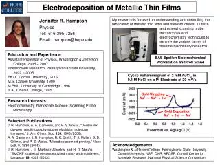
20 nm Ta Production of Hard-Magnetic FePt Films FePt alloys in the desired composition can be produced in the following fashion: FePt alloy, L10 phase Deposition of a Fe/Pt multilayer: (0.5 nm Fe/0.5 nm Pt)30, then annealing for 20 min at 700 K: Si wafer Magnetic hysteresis Direct resistive heating of the Si substrate via current flow through a thin Ta layer allows for high heating and cooling rates, thus preventing excessive grain growth during alloy formation Magneto-Optical Kerr Effect (MOKE)
The Magnetic Structure of Hard/Soft – Magnetic Bilayers Fe on FePt A soft – magnetic film (Fe) is deposited on a hard-magnetic film (FePt) with uniaxial anisotropy An exchange-spring magnet External field Exchange coupling at the interface leads to parallel alignment of Fe and FePt moments in that region. With increasing distance from the interface the magnetic coupling becomes weaker. An external field H perpendicular to the anisotropy direction thus induces spiral magnetization in the film. The moments in the soft-magnetic film return to parallel alignment when the external field is switched off. Fe FePt Direction of anisotropy (remanent magnetization after saturation) Due to this spring-like behavior, such systems are called exchange-spring magnets (E. F. Kneller and R. Hawig, IEEE Trans. Magn. 27, 3588 (1991))
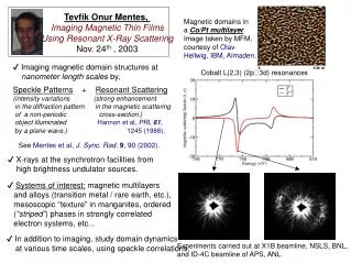
Imaging the Spin Structure of Exchange-Coupled Thin Films Isotopic probe layers of 57Fe can be used to determine the depth dependence of the spiral twist in the soft-magnetic layer: An ultrathin layer of 57Fe is embedded in the Fe film as shown below. Thus, transverse displacement Dx of the sample relative to the 200 mm wide beam of synchrotron radiation allows to probe the magnetic properties of the film as a function of depth D. H Scattering plane 11nm Fe FePt 0.7 nm 57Fe 20mm M The sample is illuminated in grazing incidence geometry with synchrotron radiation tuned to the 14.4 keV resonance of 57Fe. A synopsis of the method is given on the next slide.
Temporal beats Nuclear Resonant Scattering of Synchrotron Radiation Hyperfine interaction of the 57Fe nucleus in magnetic materials Superposition of wavetrains with slightly different frequencies leads to characteristic temporal beats From the beat pattern the magnetization direction in the sample can be derived. Due to the enormous brilliance of the synchrotron radiation, data acquisition times can be as short as a few minutes Radioactive source Synchrotron radiation Energy spectra Time spectra
160 mT 0 50 150 200 100 Time (ns) Imaging the Internal Spin Structure of Exchange-Spring Magnets Time spectra of nuclear resonant scattering Scattering plane Dx 11 nm 0.7 nm 57Fe 20mm log(intensity) 11 nm Fe 30 nm FePt R. Röhlsberger et al, Phys. Rev. Lett. 89, 237201 (2002)
160 mT 240 mT 500 mT The field dependence of the internal spin structure in exchange-spring layer systems The figures on the right show the results of the measurements for different values of the external field. These results are plotted in the graph below. The solid liens are results of simulations according to the model explained on the next slide. FePt Ag
Simulation of Exchange-Spring Layer Systems Divide the layer system into N sublayers of thickness d The equilibrium configuration of such layer systems is found by application of the following micromagnetic model (E. Fullerton et al., Phys. Rev. B 58, 12193 (1998)) Minimize the magnetic free energy of the system The total magnetic energy of a system consisting of N layers is given by: Exchange Anisotropy Dipolar energy The method allows one to determine magnetic depth profiles. Here the exchange constant changes near the upper interface due to oxidation/interdiffusion This equation is iterated with the values obtained from dE/dji = 0 until equilibrium is reached for each sublayer.