Download
1 / 1
10 likes | 154 Views
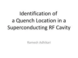
Diagnostic Instrumentation for the Fermilab Vertical Cavity Test Facility C.M. Ginsburg , R. Carcagno, M. Champion, N. Dhanaraj, A. Lunin, # W.-D. Moeller, A. Mukherjee, R. Nehring, D. Orris, J. Ozelis, V. Poloubotko, D.A. Sergatskov All Fermilab except # (DESY).

E N D
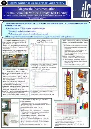
Diagnostic Instrumentation for the Fermilab Vertical Cavity Test Facility C.M. Ginsburg , R. Carcagno, M. Champion, N. Dhanaraj, A. Lunin, #W.-D. Moeller, A. Mukherjee, R. Nehring, D. Orris, J. Ozelis, V. Poloubotko, D.A. SergatskovAll Fermilab except #(DESY) • The Fermilab vertical cavity test facility (VCTF), for CW RF vertical testing of bare ILC 1.3 GHz 9-cell SRF cavities, was completed in July 2007. • Primary purpose of VCTF is to assess cavity performance • Study cavity production and processing • Perform acceptance test prior to insertion in a cryomodule • VCTF diagnostic instrumentation and measurements are required to understand cavity performance Quench Location on AES01 Cavity • Mode measurements indicate the poorly performing cell is 3 or 7 • Initial “Fast” thermometry test (8 sensors on each equator) implicates 45o region of cell 7 near equator • Comprehensive “Fast” thermometry test pinpoints quench on AES01 cell 7 AES01 quench location using “Fast” thermometry • Eight Cernox sensors • Temperature (K) vs. time (sec) over 4 quench-recovery cycles; input power constant • Temperature rise ~0.1 K over ~2 sec seen in sensors #3 and #4 before quench • Quench seen in all 8 sensors • Temperature (K) vs. transmitted power (arbitrary units) • Temperature rise seen in sensors #3 & #4 “Fast” thermometry - hot spot detection • Cernox RTD (resistive thermometry device) sensors • Calibrated, absolute temperature measurement • Flexible sensor placement, depending on test requirements • Wired in series with 1 mA current source and shunt resistor for measuring current • G10 band or nylon thread, plus Apiezon grease, used for mounting • Fast 10 kHz sampling rate suitable for quench detection and temperature rises • Status: well tested and reliable system • Successfully and repeatedly used in other test systems since 2002 • Used to pinpoint quench in AES01 cell 7 AES01 cell 7 #4 #3 Mode measurements – determine cavity performance limiting cell(s) • Determine limitation to within one (cell 5) or two cells • Measure frequencies of 8 out of 9 TM010 passband modes on network analyzer (the p/9 was not measurable) • Determine total cavity stored energy at maximum input power just before quench for each measurable passband mode • Maximum gradient for each cell extrapolated from measurement using Superfish simulation by Haipeng Wang (JLab) • Cell 3 & 7 had the lowest maximum gradient, and cause the performance limitation • Field emission observed for 7p/9 mode only 9-cell thermometry - hot spot detection • System requirements • Measure temperature rise, not absolute temperature, in a comprehensive pattern around each of the 9 cells, all 9 cells tested in a single step • Fast installation; use for “every” 9 cell test • Design • Diode sensors – 1mm x 1mm sense area, ~1cm spacing • Diodes allow multiplexing without active multiplexer • 1N4148 diode in a SOD523 package • 960 diodes per cell = 60 cards x 16 diodes/card • 8640 diodes for a 9-cell cavity • Cards: G10 boards, Kapton printed circuit, Kapton flex loop provides spring to hold diodes against surface • Cage: Cards installed once on two half-shells which bolt together • Status: Single-cell prototype being built; test CY07 R Completed card z G10 boards Kapton printed circuit Variable RF input coupler • Keeps cavity critically coupled • Facilitates mode measurements useful for cavity diagnostics • Mounts to standard input coupler port • Movement range DR~15 mm (equiv. 2×10⁹. Qext. 4×10¹⁰) • Status: Parts arriving; test CY07 Diode sensor Flex shown in compressed state as if contacting cavity