Download
1 / 54
580 likes | 764 Views
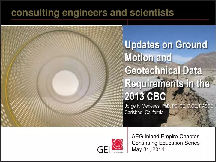
c onsulting engineers and scientists. Updates on Ground Motion and Geotechnical Data Requirements in the 2013 CBC Jorge F. Meneses, PhD, PE, GE, D.GE, F.ASCE Carlsbad, California. AEG Inland Empire Chapter Continuing Education Series May 31, 2014. Outline. Overview Design earthquakes

E N D
consulting engineers and scientists Updates on Ground Motion and Geotechnical Data Requirements in the 2013 CBCJorge F. Meneses, PhD, PE, GE, D.GE, F.ASCECarlsbad, California AEG Inland Empire Chapter Continuing Education Series May 31, 2014
Outline • Overview • Design earthquakes • Maximum direction • Risk-targeted • General procedure • Examples • Geotechnical Requirements • Summary
Building Code Cycle NEHRP 2009 ASCE 7-10 IBC 2012 2012 (Effective January 1, 2014)
Some definitions • Definitions • Hazard: a phenomenon that has the potential to cause damage • Risk: the probability that damage will occur • In general, it is accepted that Earthquake Hazard cannot be avoided • Hence, the philosophy behind building codes is to “mitigate risk” • We can’t avoid earthquakes, so we will build structures that can withstand earthquakes • Key concept: acceptable risk
MCER RISK-TARGETED MAXIMUM CONSIDERED EARTHQUAKE (MCER) GROUND MOTION RESPONSE ACCELERATION The most severe earthquake effects considered by ASCE 7-10 determined for the orientation that results in the largest maximum response to horizontal ground motions and with adjustment for targeted risk (ASCE 7-10, Chapter 11, p.60)
MCEG MAXIMUM CONSIDERED EARTHQUAKE GEOMETRIC MEAN (MCEG) PEAK GROUND ACCELERATION The most severe earthquake effects considered by ASCE 7-10 determined for geometric mean peak ground acceleration and without adjustment for targeted risk The MCEG PGA adjusted for site effects (PGAM) is used for evaluation of liquefaction, lateral spreading, seismic settlements, and other soil related issues. (ASCE 7-10, Chapter 11, p.60)
Geomean and maximum Sa (Whittaker et al 2009)
Comparison of various models SaRotD100/SaRotD50 (Shahi and Baker 2013)
Maximum Response • Ground motion values contoured on maps incorporate factors to adjust from a geometric mean to the maximum response regardless of direction • These factors are 1.1 for 0.2 second spectral response acceleration (SS) and 1.3 for 1.0 second spectral response acceleration (S1) (ASCE 7-10, Figures 22-1 through 22-6)
General procedure • Use mapped values and tables from code • USGS Seismic design maps web application
Seismic Ground Motion Values (ASCE 7-10, Chapter 11, p.65-66)
SMS, SM1 SDS, SD1 Fa , Fv Site Class B SS, S1
Site Classification (ASCE 7-10, Chapter 20, p.204)
Site Coefficient Fa (Chapter 11, p.66)
Site Coefficient Fv (Chapter 11, p.66)
SAN DIEGO SITE SITE CLASS C (Fa = 1.0, Fv = 1.3) 2.00 PGA = 0.378g MCER Site Class B 5 percent 1.75 damping MCER Site Class C SS *Fa=SMS 1.50 DE = 2/3 MCER Sa = SDS (0.4+0.6 T/To) 1.25 Sa = SD1/T SDS = 2/3*SMS=0.946 1.00 Spectral Acceleration (g) To = 0.2 SD1/SDS Ts = SD1/SDS SM1=Fv*S1 0.75 S1 0.50 PGA = 0.4 SDS = SDS/2.5 SD1 =2/3*SM1 =0.454 0.25 0.00 0.0 0.2 0.4 0.6 0.8 1.0 1.2 1.4 1.6 1.8 2.0 To=0.10 TS=0.48 Period (seconds)
Risk Category of Buildings (Chapter 1, p.2)
Seismic Design Category based on S1 (Chapter 11, p. 67)
Seismic Design Category based on SDS (Chapter 11, p. 67)
Seismic Design Category based on SD1 (Chapter 11, p. 67)
Seismic design category D through F For liquefaction studies PGAM = FPGA PGA PGAM = MCEG PGA adjusted for site effects PGA = Mapped MCEG PGAs FPGA = Site coefficients (see table) (ASCE 7-10, Section 11.8.3.2, p.68-69)
Site coefficient FPGA (ASCE 7-10, Chapter 11, p.68)
Location of three selected sites Rose Canyon- Newport-Inglewood Fault Zone Coronado Bank Fault Zone San Diego Trough Fault Zone
Comparison of SDS (Luco 2009)
SDS – Southern California (OSHPD 2012)
Maxima and Minima Values for California Maxima Ss = 3.73 g S1 = 1.28 g Minima Ss = 0.204 g S1 = 0.107 g SDS = 0.22 g SD1 = 0.17 g
Seismic design category D through F For seismic lateral earth pressures: The determination of dynamic seismic lateral earth pressures on foundation walls and retaining walls supporting more than 6 feet (1.83m) of backfill height due to design earthquake ground motions (2013 CBC, Section 1803A.5.12, p. 177)
Seismic design category D through F An assessment of potential consequences of liquefaction and soil strength loss, including, but not limited to: • Estimation of total and differential settlement • Lateral soil movement • Lateral soil loads on foundations • Reduction in foundation soil-bearing capacity and lateral soil reaction • Soil downdrag and reduction in axial and lateral soil reaction for pile foundations • Increases in soil lateral pressures on retaining walls (2013 CBC, Section 1803A.5.12, p. 177)
Seismic design category D through F Discussion of mitigation measures such as, but not limited to: • Selection of appropriate foundation type and depths • Selection of appropriate structural systems to accommodate anticipated displacements and forces • Ground stabilization • Any combination of these measures and how they shall be considered in the design of the structure (2013 CBC, Section 1803A.5.12, p. 177)