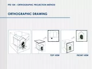
ORTHOGRAPHIC DRAWING
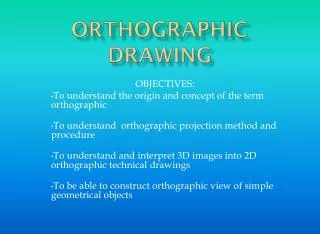
ORTHOGRAPHIC DRAWING. OBJECTIVES: To understand the origin and concept of the term orthographic To understand orthographic projection method and procedure To understand and interpret 3D images into 2D orthographic technical drawings

ORTHOGRAPHIC DRAWING
E N D
Presentation Transcript
ORTHOGRAPHIC DRAWING OBJECTIVES: To understand the origin and concept of the term orthographic To understand orthographic projection method and procedure To understand and interpret 3D images into 2D orthographic technical drawings To be able to construct orthographic view of simple geometrical objects
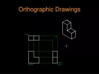
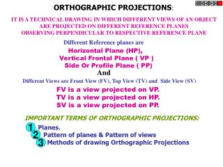
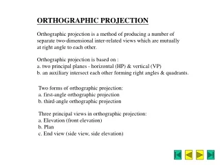
Orthographic drawing Orthographic drawing forms the base of all technical drawings. It is a system of drawing that allows 3D objects to be easily translated into 2D drawings through series of views. The system of drawing is necessary before manufacturing and construction can take place. • The term ortho-graphic is a Greek word meaning perpendicular (90⁰ angle) drawing • In orthographic drawing, views of an objects are projected onto an imaginary planes that are perpendicular to the face of the object. These imaginary planes are known as planes of projection. The 3 planes are horizontal, frontal and profile. These planes are perpendicular to one another. All non-cylindrical objects consist of 6 basic views – TOP, FRONT, RIGHT, REAR, LEFT AND BOTTOM. However, only 3 views are required to describe an object – TOP, FRONT AND RIGHT SIDE VIEWS. All other views are repetitions. The principal dimensions common to the 3 views are width(W), height(H), depth(D).
Orthographic drawing Six common views
Projection planes Projection planes
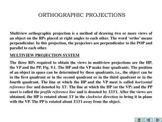
Orthographic drawing Steps and general Guidelines for orthographic construction • Select the view that shows the most important information as front view • First, select scale and layout the orthographic quadrants on the drawing paper • Then layout and construct the front view • Align and extend projection lines from all features of the front view to the top view. Layout and construct the top view. • Draw a 45º projection line (MITRE LINE) starting from the top right corner of the top view diagonally to the top of page. • Project all the features of the top view to the 45º projection line and then onto the right side view. Depth dimension is the same in both top and right side views. • Project the features of the front view to the right side view. • Make sure all views are aligned and positioned in their appropriate quadrant • Provide 50 mm space between views • Label each view accordingly • Review drawing and keep work clean