Download
1 / 14
140 likes | 379 Views
Fair Queueing Definition Parking Lot Problem Buffer Scheduling Fluid-flow FQ Packet-by-packet FQ Problem of the FFQ and PFQ Self-Clocked FQ ATC accommodation strategy stage ATM switch Switch Element (SE) Input Module (IM) Internal RM cell.

E N D
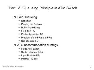
Fair Queueing Definition Parking Lot Problem Buffer Scheduling Fluid-flow FQ Packet-by-packet FQ Problem of the FFQ and PFQ Self-Clocked FQ ATC accommodation strategy stage ATM switch Switch Element (SE) Input Module (IM) Internal RM cell Part IV. Queueing Principle in ATM Switch HUFS EE Comm. Networks Lab.
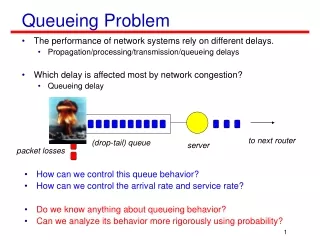
Fair Queueing (FQ) 이란? • Definition technique that allows each flow passing through a network device to have a fair share of network resources • isolation mechanism • firewall mechanism HUFS EE Comm. Networks Lab.
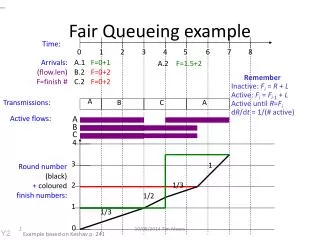
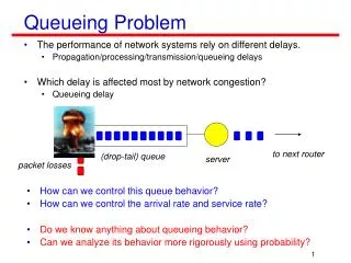
- Problem in routers - Exponentially bad fairness Nagle’s solution(1987) Output queues for each flow (in each router) Round-robin (RR) service Ignores packet length Demers et.al.(1989) Bit-by-bit RR (BR) infeasible Simulating BR : VFT ---> sorting ---> service order Fair Queueing (FQ) (주) VFT : Virtual Finishing Time • Parking Lot Problem Link L HUFS EE Comm. Networks Lab.
FCFS • Rogue flow can increase traffic above its share unfair ! • Round-robin (RR) • Equal packet length fair ! • Rogue flow with long packet unfair ! • Priority service • Preemptive priority service • Non-preemptive priority service • Fair Queueing (FQ) • Amount of service pre-specified service share • Ensuring fair access to bandwidth for a set of similar users • FQ is a generalization of the RR discipline. • RR : fixed service order • FQ : non-fixed service order • Buffer Scheduling HUFS EE Comm. Networks Lab.
Fluid-flow FQ • Fluid-flow Fair Queueing (FFQ) • Demer et al, 1989 • Fluid-flow traffic model parallel service • Idealized fair queueing • Only applicable to a hypothetical fluid-flow traffic model • Impossible to implement rk : service share of session k HUFS EE Comm. Networks Lab.
Pkt-by-Pkt FQ • Packet-by-packet Fair Queueing (PFQ) • Weighted FQ (WFQ) • Demer et al, 1989 and Parekh et al, 1992 • Packet-by-packet service • FFQ system is assumed to be underlined • Virtual Finishing Time (VFT) is calculated • VFT determines service orders of packets • Each packet is serviced within ( + VFT of FFQ) : transmission time of the longest packet • Nearly perfect but impossible to high speed applications HUFS EE Comm. Networks Lab.
k backlogged sessions are simultaneously served. • k sessions become “absent” during • k breakpoints on • k times calculation of during • ATM environment • 1 cell transmission time ~ a few microseconds • Several hundred simultaneous connections • Several hundred calculation of during a few microseconds. • Impossible to implement the FFQ/PFQ algorithm in high speed network • Problem of the FFQ and PFQ HUFS EE Comm. Networks Lab.
Self-Clocked FQ(SCFQ) • Hypothetical fluid-flow queueing system is removed • Approximate of PFQ • Virtual time is referenced to the actual queueing system itself • “self-clocked” • VFT reference for each flow (PFQ) • Single reference for all flows (SCFQ) : reduced complexity : applicable to high speed applications • Nearly optimal FQ scheme HUFS EE Comm. Networks Lab.
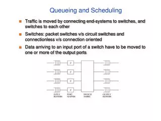
ATC Accommodation Strategy • 3-stage ATM Switch • Real-time traffic should not be disturbed by non-real time traffic. • buffer separation in SE • Different connections in an IM go through different switchpaths. Different paths have different conditions. • VC queueing in the IM HUFS EE Comm. Networks Lab.
3-stage ATM Switch (cont.) • Interface Module (IM) • 5 traffic classes: CBR, rt-VBR, nrt-VBR, ABR,UBR • Class buffers for each CBR, rt-VBR and nrt-VBR class • VC buffers for each ABR and UBR connections • Internal RM cells for ABR and UBR connections ex) iFRM(ABR), iFRM(UBR), iBRM(ABR), iBRM(UBR) • Prioritized scheduling between classes FQ between VCs in the ABR and UBR class • Switch Element (SE) • Multi-class buffers per port ex) real-time and non-real-time buffer • Prioritized scheduling between classes HUFS EE Comm. Networks Lab.
Switch Element (SE) : example • Real-time traffic : CBR, rt-VBR • Non-real-time traffic : nrt-VBR, ABR,UBR • BP >TH1 ==> Congestion marking on iFRM(UBR) • BP >TH2 ==> Congestion marking on iFRM(UBR) and iFRM(ABR) HUFS EE Comm. Networks Lab.
Input Module : example HUFS EE Comm. Networks Lab.
Scheduler 1 : Weighted FQ • Scheduler 2 : Priority service • Preemptive or Non-preemptive ? • Weighted FQ is also considered • Traffic descriptor for FQ Can we guarantee QOS for the real-time traffic ? • Input Module : example (cont.) HUFS EE Comm. Networks Lab.
IM(U) : up-stream handling circuit • ABR : FRM iFRM(ABR) • UBR : periodically generates new iFRM(UBR) • We mark congestion on each iFRM if VC buffer exceeds threshold • SE (Switch Element) • Congestion marking at each SE • Switch fabric (SF) must provide for information that the IM can determine whether each ABR and UBR connection has suffered congestion or not • ex) SFmonitors the utilization of each output link and/or buffer state for non-real time traffic. Then marks on a specific field of the iFRMs • IM(D) : down-stream handling circuit • ABR, 1) iFRM(ABR) ---> iBRM(ABR) ==> return to IM(U) : A new iBRM(ABR) is generated before the first BRM is received 2) iFRM(ABR) ---> FRM ==> return to NNI • UBR : iFRM(UBR) ---> iBRM(UBR) ==> return to IM(U) • Internal RM cell HUFS EE Comm. Networks Lab.