Download
1 / 14
140 likes | 269 Views
This guide delves into the essential components of PWM (Pulse Width Modulation) inputs used in robot controllers, including color-coded wiring for voltage, signal, and ground. It contrasts analog and digital signals, explaining their roles in controlling motors and sensors. The section on programming highlights the evolution from traditional RC programming to modern platforms like NI Compact RIO and VEX's EasyC, emphasizing debugging practices and code management. Understanding these concepts will optimize troubleshooting and enhance programming efficiency for robotics enthusiasts.

E N D
Introduction to Inputs By Mike He, Anindya Basu and Christopher Lin
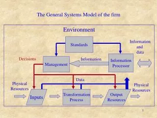
PWM’s Voltage Signal Ground • Inputs are carried through a 3-wire called a PWM (Pulse width modulator) cable to the Robot Controller Connectors Crimps
Wires come in different colors, but you should be able to tell what they mean. • Red normally voltage • Yellow or white normally Signal • Ground normally black • Two kinds, male and female (a.k.a. with pin and without) • Color coding important, easier to troubleshoot if there is a problem
Analog Signal vs. Digital Signal • Analog is from 0 to 255 • Value differs depending on the voltage sent, often from 0 to 5 volts. • Analog Signal is used for motors and some sensors. • Digital is from 0 to 1, and the voltage differs from HIGH to LOW. • Digital signal can be used for simple sensors, such as limit switches, or more complicated sensors using extremely fast pulses
Digital Signal and Binary • Digital signal pulses REALLY FAST • Pulses converted to 0 and 1 • Sequence of pulses then converted to a number • Ex: 0001 is 1, 0010 is 2 etc. • RC treats a specific number of pulses as one set of inputs
IFI Robot Controller • Old RC • Received inputs through digital and analog slots • Programmable using C.
NI Compact RIO • New Robot Controller • Modular system • Programmable using C, C++, or Labview (graphical) • Beefier!
AND NOW INTRODUCING (Sorta)...
Vex and Easy C • You’ll be programming this in EasyC and later, many you have already programmed the vex • Easy C graphical programming environment • Easier for people without prior programming experience to program
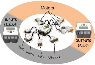
Some sensors you will be using on the VEX • Bumper/Limit Switch • Both digital signals, alert you when they is pressed. • Useful for detecting when a object strikes the sensor • Ex: stop the motors after an elevator hits full bottom
Debugging • If there is a problem, it is probably YOUR fault, not the RC or the computer or mine(maybe…) • Good programming practices very important, hieroglyphics vs english • Easy understandability helps debugging • Bad code may be interesting, but it is hard to figure out • Follow logic of the code
Debugging (continued) • Print out values to get a sense of what the program is doing • You might get unexpected results, figure out why it occurs • Make sure everything is doing what you want it to do, no loopholes • Comment things, so others may help you debug and understand your code faster
Saving Code • A few things to remember: • Easy to recognize/read and in a accessible location, normally this is under the R file (we’ll show you later) • Safe often, and don’t save on the same file (save as, not save).