Download

1 / 24
240 likes | 373 Views
Current, Resistance,Voltage Electric Power & Energy Series, Parallel & Combo Circuits with Ohm’s Law, Combo Circuits with Kirchoff’s Laws. Review for Chapters 19-20. Current (I). The rate of flow of charges through a conductor Needs a complete closed conducting path to flow

E N D
Current, Resistance,VoltageElectric Power & EnergySeries, Parallel & Combo Circuits with Ohm’s Law,Combo Circuits with Kirchoff’s Laws Review for Chapters 19-20
Current (I) • The rate of flow of charges through a conductor • Needs a complete closed conducting path to flow • End of the conducting path must have a potential difference (voltage) • Measured with an “ammeter” in amps (A) named for Ampere – French scientist CIA C= current I= variable A=amps
Voltage (V) • Electric potential difference between 2 points on a conductor • Sometimes described as “electric pressure” that makes current flow • Supplies the energy of the circuit • Measured in Volts (V) using a voltmeter
Resistance (R) • The “electrical friction” encountered by the charges moving through a material. • Depends on material, length, and cross-sectional area of conductor • Measured in Ohms (Ω)
Ohm’s Law • A relationship between voltage, current, and resistance in an electric circuit • used to make calculations in all circuit problems • V = potential difference (voltage) in volts • I = electric current in amperes (amps , A) • R = resistance in ohms ( )
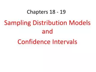
resistor switch ammeter battery A Circuit Schematics • Simple Circuit A With a voltmeter attached outside the loop V
Using Meters in Electricity Labs • Ammeter • measures current in amps or milliAmps • connect wire from negative side of battery to • the black peg. Some clips can go right in the top, • others work better if you loosen the cap and • come in from the side/ bottom. • Connect positive wire to 5A first and see if it • registers, if not move to 500mA peg or to 50mA • To read/measure- Use the scale that matches the • red connector you plugged into • Voltmeter (think VP) • Measures voltage/potential difference • Used in parallel ONLY - it should be plugged in outside the “circle” • If wired into the circuit you will fry its little brain!! • CAN NOT use 5 reading with a 6V battery! Start with 10 (2/10th markers) • and go to 15 if needed (each line ~ .35)
A Circuit with Series of Resistors • Current can only travel through 1 path add resistances • Rs=R1+ R2 +R3 +… • Current (amp) is the same through all parts R1 R2 R3
R1 = 1Ω R2 = 1Ω A Voltage Drop Across Resistors • Current (amp) is the same through all parts • Sum of the voltage drop must equal the source voltage 6 V
Electric Power (Watts) Power = Current x Voltage Watts = amps x volts 60W 60W 60W 120V 120V
Electric Energy • Recall that Power = Work Time and that it requires Energy to do work so we could say Power = ∆Energy Time • Electric energy can be measured in Joules (J) or Kilowatt hours ( kWh ) • for Joules use Power in watts and time in seconds • for kWh use Power in kilowatts and time in hours
Power, Current, Electric Potential, and Resistance • Power = ∆ Energy Time • Icurrent = Q time • ∆V = ∆PE Q • I = V R so . . . P = V x I P = V2 R
R1 R2 R3 Series Circuits • Current can only travel through one path • Current is the same through all parts of the circuit. • The sum of the voltages of each component of the circuit must equal the battery. • The equivalent resistance of a series circuit is the sum of the individual resistances. V I
Solving a Series Circuit Step 1: Find the equivalent (total) resistance of the circuit R1=1 Ω IT 6V R2=1 Ω Step 2: Find the total current supplied by the battery Step 3: Find Voltage Drop across each resistor. Note: Since both resistors are the same, they use the same voltage. Voltage adds in series and voltage drops should add to the battery voltage, 3V+3V=6V
R1 R2 V R3 Parallel Circuits • Current splits into “branches” so there is more than one path that current can take • Voltage is the same across each branch • Currents in each branch add to equal the total current through the battery
R2=2Ω 12V R3=3Ω R1=1Ω Solving a Parallel Circuit Step 1: Find the total resistance of the circuit. Step 3: Find the current through each resistor. Remember, voltage is the same on each branch. Step 2: Find the total current from the battery. Step 4: Check currents to see if the answers follow the pattern for current. The total of the branches should be equal to the sum of the individual branches.
Series Current Same Voltage Adds V1 + V2 + . . . RT = R1 + R2 + . . . Parallel Current Adds Voltage Same I1 + I2 + I3 + . . . R2=2Ω R3=3Ω R1=1Ω R1 = 2Ω R2 = 3Ω A Comparing Series & Parallel
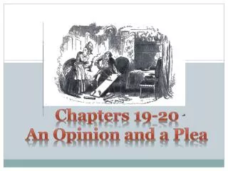
Combo Circuits with Ohm’s LawWhat’s in series and what is in parallel? A B It is often easier to answer this question if we redraw the circuit. Let’s label the junctions (where current splits or comes together) as reference points. 5Ω 1Ω 3Ω 6Ω 15V D C 4Ω 7Ω 2Ω 6Ω 4Ω C 2Ω B 1Ω D 7Ω A 3Ω 5Ω 15V
Combo Circuits with Ohm’s LawNow…again…what’s in series and what’s in parallel? 6Ω 4Ω 2Ω C B The 6Ω and the4Ω resistors are in series with each other, the branch they are on is parallel to the 1Ω resistor. The parallel branches between B & D are in series with the 2Ω resistor. The 5Ω resistor is on a branch that is parallel with the BC parallel group and its series 2Ω buddy. The total resistance between A & D is in series with the 3Ω and the 7Ω resistors. 1Ω D A 7Ω 3Ω 5Ω 15V
Combo Circuits with Ohm’s LawFinding total (equivalent) resistance 6Ω 4Ω 2Ω C B To find RT work from the inside out. Start with the 6+4 = 10Ω series branch. So, 10Ω is in parallel with 1Ω between B&C… Then, RBC + 2Ω=2.91Ω and this value is in parallel with the 5Ω branch, so… 1Ω D A 7Ω 3Ω 5Ω Finally RT = RAD +3 + 7 = 1.84 + 3 + 7 RT = 11.84Ω 15V
Combo Circuits with Ohm’s LawSolving for current and voltage drops in each resistor RT = 11.84Ω IT=1.27A IT=1.27A 6Ω 4Ω 2Ω C Then… B The total current IT goes through the 3Ω and the 7Ω and since those are in series, they must get their chunk of the 15V input before we can know how much is left for the parallel. So… 1Ω D A 7Ω 3Ω So… Since parallel branches have the same current, that means the voltage across the 5Ω resistor V5Ω=4.84V and the voltage across the parallel section between B&C plus the 2Ω is also 4.84V 5Ω 15V
Combo Circuits with Ohm’s LawSolving for current and voltage drops in each resistor (continued) I2Ω=0.81A I5Ω=0.46A IT=1.27A IT=1.27A Known values from previous slide. 6Ω 4Ω To calculate the top branch of the parallel circuit between points A & D we need to find the current and voltage for the series 2 Ω resistor. Since the current through the resistor plus the 0.92A for the bottom branch must equal 1.3A. 2Ω C To calculate the current through the 5Ω resistor… B 1Ω D A 7Ω 3Ω 5Ω 15V So…
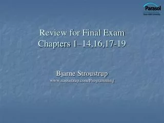
Combo Circuits with Ohm’s LawSolving for current and voltage drops in each resistor (continued) I6Ω=I4Ω =0.068A Known values from previous slide. I1Ω=0.68A I2Ω=0.81A I5Ω=0.46A IT=1.27A IT=1.27A 2Ω Next we need to calculate quantities for the parallel bunch between points B&C. The voltage that is left to operate this parallel bunch is the voltage for the 5Ω minus what is used by the series 2Ω resistor. The 1Ω resistor gets all of this voltage. Finally we need to calculate the current through the 6Ω and 4Ω resistors and the voltage used by each. C B 6Ω 4Ω 1Ω D A 7Ω 3Ω All we need now is the voltage drop across the 6Ω and 4Ω resistors. So… 5Ω 15V THE END!