Download
1 / 23
230 likes | 400 Views
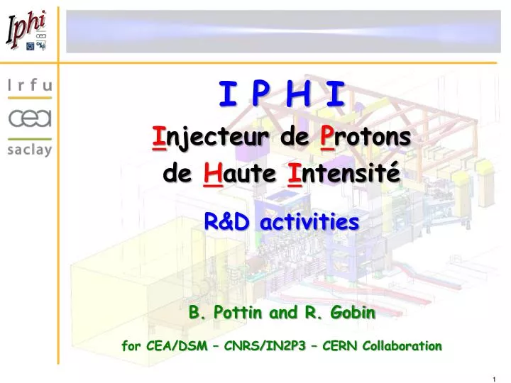
I P H I I njecteur de P rotons de H aute I ntensité R&D activities B. Pottin and R. Gobin for CEA/DSM – CNRS/IN2P3 – CERN Collaboration . IPHI: low energy HPPA demonstrator. RFQ 100mA/3MeV/352MHz. 4 electrodes. Diagnostic Line 100mA/3MeV/CW.

E N D
I P H I Injecteur de Protons de Haute Intensité R&D activities B. Pottin and R. Gobin for CEA/DSM – CNRS/IN2P3 – CERN Collaboration
IPHI: lowenergy HPPA demonstrator RFQ 100mA/3MeV/352MHz 4 electrodes Diagnostic Line 100mA/3MeV/CW Developments and construction started at the end of 90's. SILHI source 100mA/95keV/CW
RFQ module construction • 6 m long RFQ made of 6 modules… • Each module is built in 4 parts corresponding to 4 electrodes • with very tight tolerances : few microns/1m. • machining and alignment are very important. • ASSEMBLY by BRAZING • surface of the brazing plans (cleanliness, flatness, roughness…) is critical. < 10 mm 50mm 0.3m 1m
RFQ assembly challenges • Vacuum challenge • P = 10-7 mbar • No leak with 268 cooling pipes • Numerous ports (60 pumping ports, 4 RF ports, 96 tuners) • 75 crossings through the brazing plan for each module (cooling pipes) • No pollution • brazing surface • Deformation of geometry after brazing <10µm with elongation of about 16mm @ 800°C during the brazing process (brazing material is AgCuPd) Thermal treatments before final machining
Brazing preparation • Creation of a cleaning laboratory • To test different chemical solutions • To test different cleaning procedures with: • Ultrasonic bath (warming or not) • Rinsing method with demineralized water (warming or not) • Cleaning of several materials: • Copper, stainless steel, molybdenum… • Storage with N2 saturated atmosphere • Cleanliness of the surfaces to avoid oven pollution After Before
Horizontal or vertical brazing • Brazing groove design depends on module brazing position: • Longitudinally for horizontal brazing • Fish bones shape (with external access) for vertical position • R&D activities allowed us obtaining better results with the vertical brazing solution : • - less deformations • - possibility to repair with a second brazing (fish bones grooves are empty after the brazing) • For both cases, specific local grooves for the extremities and cooling pipes
R&D in layer deposition • The RF adjustments are done by modifying the volume inside the cavity by tuners RF feeding leads to cavity thermal heating. • To help cooling of the tuner flanges, copper layer deposition is needed.
R&D in layer deposition • material deposition needed for: • 2µm thick Nickel (brazing stainless steel with copper) • 25µm thick Copper (thermal transfer) • Developments (with external company) of new tools and process to get reproducible thickness
R&D on bi-material pieces WHY ? • a vacuum leak appeared between stainless steel flange and copper of the module after 2nd brazing of module 6 • Looks to be caused by the fragility of the nickel layer • decision to use bi-material pieces with high temperature brazing (AuNi) between stainless steel and copper without nickel followed by classical brazing copper-copper
R&D : brazing for different assembly • Face to the cost of AuNi brazing technique, general R&D program is in progress to qualify the mechanical resistance of different material assemblies after brazing. • The aim is to be able to decide wich brazing material is appropriate versus the mechanical application. • The following brazing materials are under test: • Cusil : 72%Ag + 25%Cu – 780°C • Palcusil 10 : 58%Ag + 32%Cu + 10%Pd – 852°C • Nioro : 82%Au + 18%Ni – 955°C • 50Gold50Copper : 50%Au + 50%Cu – 970°C • 35Gold65Copper : 35%Au + 65%Cu – 1010°C Nioro Palculsil 10
Brazing with no displacement… To prevent possible displacements: • Longitudinal displacement : a glidcop conical pin (same expansion than copper) to help the mechanical assembly and to keep mechanical resistance during the brazing • General brazing: Clamping with Molybdenum rods, stainless steel nuts and inconel “belleville” washers with arrangement validated by preliminary tests Glidcopconic pin • - Transversal displacement : copper pin brazed to get correct expansion and minimize leak risks in the brazing plan CUC2 pin
Displacements after brazing IPHI’s module 6th : • Maximum displacement of 35 µm has been observed at the extremity of left minor pole (compare to machining) • Average displacements of 15 µm Theoric After machining Before 1st brazing After 1st brazing After 2nd brazing No consequences appeared in particle dynamics and RF simulations
RF measurements • Bead pull measurement method has been developed and qualified with the IPHI project • It allows qualifying geometric defaults lower than 50 µm and adjusting the stub tuner dimensions QQ SQ TQ
Codes (DAPHPC) Infrastructure IPHI Ion Sources (BETSI) Diagnostics (ECRIS+LBE+LHE) Developments around IPHI Spiral 2 end to end deuteron beam simulations IPHI installation Beam profile with CCD camera Doppler 3D view of the SILHI source
SILHI source and LEBT ECR Source Resonancezone: = e B / m , pulsation e, electron charge B, magneticfield m, electron mass. 2.45 GHz 875 Gauss Since 1996, SILHI produces H+ beamswith good characteristics: H+ Intensity > 100 mA at 95 keVH+ fraction > 80 % Beam noise < 2% 95 % < Reliability < 99.9 % Emittance < 0.2 mm.mrad CW or pulsedmode operation
Blindage Région d’extraction B << Bobines Ridged Transition Pumping port 5 electrode extraction system Plasma Chamber Magneticshielding Permanent magnet rings From SILHI to new sources Source design and developments are based on simulations and experiments. Permanent magnet source for Spiral 2 (5 mA – 40 keV D+ beam) and 4 electrode extraction system for IFMIF Injector (140 mA – 100 keV D+ beam). Design of FAIR injector will start soon More than 100 mA H+ beam has been extracted from a permanent magnet source. SOLMAXP code development
BETSI test bench In parallel, R&D activities are carried out for better source and beam knowledge. • Magnetic structure studies (thesis started Oct. 2009) • Analysis of RF coupling to plasma • Diagnostic development (ex: tomography within DITANET network) • New source (ALISES) under construction to be tested end 2011 • Patent n° FR1060578 • ALISES: Advanced Light Ion Source Extraction System
LBE Emittance scanner Allison scanner to characterize a 17 kW beam with high power density (1 to 2 kW/cm²) is developed - Cu block coveredwith W tilesby brazing - Water coolingsystem to assume the heating due to the beam power BEAM Prototype for brazing (W-Cu) technique validation
Species fraction analysis with fiberscope • Optical diagnostics development • Measurement of species fractions (and associated beam profiles) with Doppler shift method: • Beam image carrying with fiberscope outside the vault to a monochromatorassociated to a CCD camera FUJIKURA fiberscope on SILHI Whole beam H+(a) Species fraction observation with Doppler shift method using FUJIKURA fiberscope
A.C.C.T. Dipole magnet Quadrupoles magnets Wire scanner Pick up R.F.Q. Pump CCD cameras D.C.C.T. Steerer B.P.M. Beam stopper B.P.M. B.P.M Pumps Bergoz ACCT IPHI Diagnostic Beam Line Designed and built by CNRS • Diagnostics: • Intensity measurements: 1 D.C.C.T et 1 A.C.C.T • Beam Position Measurement: 6 P.U. • Energy measurement: 3 P.U. • Energy spread measurement: 2 slits + 1 F.C. • Transverse profiles: • 1 W.S., optical measurements, backscattered protons • Temperature measurements of the beam pipe (thermocouples) • Optical diagnostics R&D activities carried out at IPN Orsay for BPM and WS diagnostics.
Schedule of IPHI project Tr 4 • Summer 2011 : • Modules reception • End 2011 : • RFQ assembly • Summer 2012 : • Conditionning • End 2012 : • First proton beam Tr 5