
Mechatronics: Engineering for the Future
E N D
Presentation Transcript
MECHATRONICS Cross 11, Tapovan Enclave Nalapani Road, Dehradun 248001 Email: info@iskd.inContact : +918979066357, +919027669947
1. What is “Mechatronics”? Mechatronics is an interdisciplinary engineering field encompassing electrical engineering, mechanical engineering, computer engineering, telecommunications engineering, and a few other forms of engineering. The skills taught include electrical, mechanical, and computer technologies. Mechatronics technicians will usually assist the design, development and engineering staff, as well as work closely with others to install, maintain, modify and repair mechatronic systems, equipment and component parts.
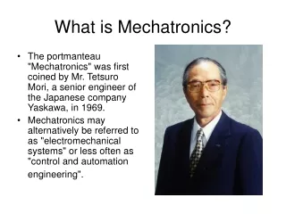
As technology advances over time, various subfields of engineering have succeeded in both adapting and multiplying. The intention of mechatronics is to produce a design solution that unifies each of these various subfields. Originally, the field of mechatronics was intended to be nothing more than a combination of mechanics and electronics, hence the name being a portmanteau of mechanics and electronics; however, as the complexity of technical systems continued to evolve, the definition had been broadened to include more technical areas. A mechatronics engineer unites the principles of mechanics, electronics, and computing to generate a simpler, more economical and reliable system. The term "mechatronics" was coined by Tetsuro Mori, the senior engineer of the Japanese company Yaskawa in 1969. An industrial robot is a prime example of a mechatronics system; it includes aspects of electronics, mechanics, and computing to do its day-to-day jobs.
Mechatronicscan also be termed as replacement of mechanics with electronics or enhance mechanics with electronics. For example, in modern automobiles, mechanical fuel injection systems are now replaced with electronic fuel injection systems. This replacement made the automobiles more efficient and less pollutant. • With the help of microelectronics and sensor technology, mechatronics systems are providing high levels of precision and reliability. It is now possible to move (in x – y plane) the work table of a modern production machine tool in a step of 0.0001 mm. • By employment of reprogrammable microcontrollers/microcomputers, it is now easy to add new functions and capabilities to a product or a system. Today’s domestic washing machines are “intelligent” and four-wheel passenger automobiles are equipped with safety installations such as air-bags, parking (proximity) sensors, anti-theft electronic keys etc.
2. Importance of Mechatronics in automation • Today’s customers are demanding more variety and higher levels of flexibility in the products. Due to these demands and competition in the market, manufacturers are thriving to launch new/modified products to survive. It is reducing the product life as well as lead-time to manufacture a product. It is therefore essential to automate the manufacturing and assembly operations of a product. There are various activities involved in the product manufacturing process. • Mechatronics concurrently employs the disciplines of mechanical, electrical, control and computer engineering at the stage of design itself. Mechanical discipline is employed in terms of various machines and mechanisms, where as electrical engineering as various electric prime movers viz. AC/DC, servo motors and other systems is used. Control engineering helps in the development of various electronics-based control systems to enhance or replace the mechanics of the mechanical systems. Computers are widely used to write various softwares to control the control systems; product design and development activities; materials and manufacturing resource planning, record keeping, market survey, and other sales related activities.
Using computer aided design (CAD) three-dimensional models of products can easily be developed. These models can then be analyzed and can be simulated to study their performances using numerical tools. These numerical tools are being continuously updated or enriched with the real-life performances of the similar kind of products. These exercises provide an approximate idea about performance of the product/system to the design team at the early stage of the product development. sequential design process. • CAD-CAE generated final designs are then sent to the production and process planning section. Mechatronics based systems such as computer aided manufacturing (CAM): automatic process planning, automatic part programming, manufacturing resource planning, etc. uses the design data provided by the design team. Based these inputs, various activities will then be planned to achieve the manufacturing targets in terms of quality and quantity with in a stipulated time frame. • Mechatronics based automated systems such as automatic inspection and quality assurance, automatic packaging, record making, and automatic dispatch help to expedite the entire manufacturing operation. These systems certainly ensure a supply better quality, well packed and reliable products in the market. Automation in the machine tools has reduced the human intervention in the machining operation and improved the process efficiency and product quality. Therefore it is important to study the principles of mechatronics and to learn how to apply them in the automation of a manufacturing system.
3. Mechatronics system A system can be thought of as a box or a bounded whole which has input and output elements, and a set of relationships between these elements. Figure 1.1.4 shows a typical spring system. It has ‘force’ as an input which produces an ‘extension’. The input and output of this system follows the Hooke’s law F = –kx, where F is force in N, x is distance in m and k is stiffness of the spring.
A Mechatronics system integrates various technologies involving sensors, measurement systems, drives, actuation systems, microprocessor systems and software engineering. Figure 1.1.5 shows the basic elements of a mechatronicssystem. To replace the mechanics of this mechanical system with an equivalent mechatronics based system, we need to have the basic controlling element, a microprocessor. Microprocessor processes or utilizes the information gathered from the sensor system and generates the signals of appropriate level and suitable kind (current or voltage) which will be used to actuate the required actuator viz.
The input to the system is a force which can be sensed by suitable electro-mechanical sensors viz. piezo-electric device or strain gauges. These sensors generate either digital signals (0 or 1) or analogue signals (milli-volts or milli-amperes). These signals are then converted into right form and are attenuated to a right level which can properly be used by the microprocessor to take generate the actuation signals. Various electronics based auxiliary devices viz. Analogue-to-Digital Converter (ADC), Digital-to-Analogue Converter (DAC), Op-amps, Modulators, Linearization circuits, etc. are used to condition the signals which are either received by the microprocessor from the sensors or are sent to the actuators from the microprocessor. This mechatronics based spring-mass system has the input signals in the digital form which are received from the ADC and Piezo-electric sensor. The digital actuation signals generated by the microprocessors are converted into appropriate analogues signals. These analogue signals operate the hydraulic pump and control valves to achieve the desired displacement of the piston-rod.
Mechatronics: products and systems in manufacturing Mechatronicshas a variety of applications as products and systems in the area of ‘manufacturing automation’. Some of these applications are 1. Computer numerical control (CNC) machines 2. Tool monitoring systems 3. Advanced manufacturing systems a. Flexible manufacturing system (FMS) b. Computer integrated manufacturing (CIM) 4. Industrial robots 5. Automatic inspection systems: machine vision systems 6. Automatic packaging systems • Now, let us know in brief about these applications one by one.
1. Computer numerical control (CNC) machines • CNC machine is the best and basic example of application of Mechatronics in manufacturing automation. Efficient operation of conventional machine tools such as Lathes, milling machines, drilling machine is dependent on operator skill and training. Also a lot of time is consumed in workpart setting, tool setting and controlling the process parameters viz. feed, speed, depth of cut. Thus conventional machining is slow and expensive to meet the challenges of frequently changing product/part shape and size.
2. Tool monitoring systems Uninterrupted machining is one of the challenges in front manufacturers to meet the production goals and customer satisfaction in terms of product quality. Tool wear is a critical factor which affects the productivity of a machining operation. Complete automation of a machining process realizes when there is a successful prediction of tool (wear) state during the course of machining operation. Mechatronics based cutting tool-wear condition monitoring system is an integral part of automated tool rooms and unmanned factories. These systems predict the tool wear and give alarms to the system operator to prevent any damage to the machine tool and workpiece. Therefore it is essential to know how the mechatronics is helping in monitoring the tool wear. Tool wear can be observed in a variety of ways. These can be classified in two groups (Table 1.2.1). Table 1.2.1 Tool monitoring systems
3.1Flexible Manufacturing System • Nowadays customers are demanding a wide variety of products. To satisfy this demand, the manufacturers’ “production” concept has moved away from “mass” to small “batch” type of production. Batch production offers more flexibility in product manufacturing. To cater this need, Flexible Manufacturing Systems (FMS) have been evolved. • FMS is a manufacturing cell or system consisting of one or more CNC machines, connected by automated material handling system, pick-and-place robots and all operated under the control of a central computer. It also has auxiliary sub-systems like component load/unload station, automatic tool handling system, tool pre-setter, component measuring station, wash station etc. Figure 1.2.4 shows a typical arrangement of FMS system and its constituents. Each of these will have further elements depending upon the requirement as given below,
A. Workstations • CNC machine tools • Assembly equipment • Measuring Equipment • Washing stations B. Material handing Equipment • Load unload stations (Palletizing) • Robotics • Automated Guided Vehicles (AGVs) • Automated Storage and retrieval Systems (AS/RS) C. Tool systems • Tool setting stations • Tool transport systems
D. Control system • Monitoring equipments • Networks • It can be noticed that the FMS is shown with two machining centers viz. milling center and turning center. Besides it has the load/unload stations, AS/RS for part and raw material storage, and a wire guided AGV for transporting the parts between various elements of the FMS. This system is fully automatic means it has automatic tool changing (ATC) and automatic pallet changing (APC) facilities. The central computer controls the overall operation and coordination amongst the various constituents of the FMS system. • Video attached herewith gives an overview of a FMS system
The characteristic features of an FMS system are as follows, 1. FMS solves the mid-variety and mid-volume production problems for which neither the high production rate transfer lines nor the highly flexible stand-alone CNC machines are suitable. 2. Several types of a defined mix can be processed simultaneously. 3. Tool change-over time is negligible. 4. Part handling from machine to machine is easier and faster due to employment of computer controlled material handling system. Benefits of an FMS • Flexibility to change part variety • Higher productivity • Higher machine utilization • Less rejections • High product quality • Reduced work-in-process and inventory • Better control over production • Just-in-time manufacturing • Minimally manned operation • Easier to expand
3.2Computer Integrated Manufacturing (CIM) • CIM basically involves the integration of advanced technologies such as computer aided design (CAD), computer aided manufacturing (CAM), computer numerical control (CNC), robots, automated material handling systems, etc. Today CIM has moved a step ahead by including and integrating the business improvement activities such as customer satisfaction, total quality and continuous improvement. These activities are now managed by computers. Business and marketing teams continuously feed the customer feedback to the design and production teams by using the networking systems. Based on the customer requirements, design and manufacturing teams can immediately improve the existing product design or can develop an entirely new product. Thus, the use of computers and automation technologies made the manufacturing industry capable to provide rapid response to the changing needs of customers.
4. Industrial robots Industrial robots are general-purpose, re-programmable machines which respond to the sensory signals received from the system environment. Based on these signals, robots carry out programmed work or activity. They also take simple independent decisions and communicate/interact with the other machines and the central computer. Robots are widely employed in the following applications in manufacturing [3]: • Parts handling: it involves various activities such as- • Recognizing, sorting/separating the parts • Picking and placing parts at desired locations • Palletizing and de-palletizing • Loading and unloading of the parts on required machines
B. Parts processing: this may involves many manufacturing operations such as • Routing • Drilling • Riveting • Arc welding • Grinding • Flame cutting • Deburring • Spray painting • Coating • Sand blasting • Dip coating • Gluing • Polishing • Heat treatment
C. Product building: this involves development and building of various products such as: • Electrical motors • Car bodies • Solenoids • Circuit boards and operations like o Bolting • Riveting • Spot welding • Seam welding • Inserting • Nailing • Fitting • Adhesive bonding • Inspection
5. Automatic quality control and inspection systems • Supply of a good quality product or a system to the market is the basic aim of the manufacturing industry. The product should satisfy the needs of the customers and it must be reliable. To achieve this important product-parameter during a short lead time is really a challenge to the manufacturing industry. This can be achieved by building up the ‘quality’ right from the product design stage; and maintaining the standards during the ‘production stages’ till the product-delivery to the market. • A number of sensors and systems have been developed that can monitor quality continuously with or without the assistance of the operator. These technologies include various sensors and data acquisition systems, machine vision systems, metrology instruments such as co-ordinate measuring machine (CMM), optical profilometers, digital calipers and screw gauges etc. Now days the quality control activities are being carried out right from the design stage of product development. Various physics based simulation software is used to predict the performance of the product or the system to be developed. In the manufacture of products such as spacecrafts or airplanes, all the components are being critically monitored by using the digital imaging systems throughout their development.
References: • 1. HMT Ltd. Mechatronics, Tata McGraw‐Hill, New Delhi, 1988. • 2. H. Chelladurai, V. K. Jain and N. S. Vyas, Development of a cutting tool condition monitoring system for high speed turning operation by vibration and strain analysis, Int. J. Adv. Manuf. Technol. 2008, 37:471–485. • 3. P. N. Rao, CAD/CAM Principles and Applications, Tata McGraw Hill, 2011.