Download
1 / 7
70 likes | 197 Views
Static Route 1/3. Net1 192.168.1.x Gw192.168.1.253. Net2 192.168.2.x Gw192.168.2.254. Net3 192.168.3.x Gw192.168.3.254. DGS-3324SR_1. DGS-3324SR_2. Net1 192.168.1.x Gw192.168.1.254. Net4 192.168.4.x Gw192.168.4.254. Net5 192.168.5.x Gw192.168.5.254. Objective:

E N D
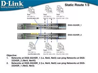
Static Route 1/3 Net1 192.168.1.x Gw192.168.1.253 Net2 192.168.2.x Gw192.168.2.254 Net3 192.168.3.x Gw192.168.3.254 DGS-3324SR_1 DGS-3324SR_2 Net1 192.168.1.x Gw192.168.1.254 Net4 192.168.4.x Gw192.168.4.254 Net5 192.168.5.x Gw192.168.5.254 • Objective: • Networks at DGS-3324SR_1 (i.e, Net2, Net3) can ping Networks at DGS-3324SR_2 (Net4, Net45) • Networks at DGS-3324SR_2 (I.e, Net4, Net5) can ping Networks at DGS-3324SR_1 (Net2, Net3)
Static Route 2/3 PROCEDURE: AT DGS-3324SR_ 1(top) 1. Configure VLAN and IP interfaces. config vlan default delete 1:1-1:24 create vlan v101 tag 101 config vlan v101 add untagged 1:1-1:8 create ipif net1 192.168.1.253/24 v101 state enabled create vlan v102 tag 102 config vlan v102 add untagged 1:9-1:16 create ipif net2 192.168.2.254/24 v102 state enabled create vlan v103 tag 103 config vlan v103 add untagged 1:17-1:24 create ipif net3 192.168.3.254/24 v103 state enabled 2. Create Static Route create iproute 192.168.4.0/24 192.168.1.254 create iproute 192.168.5.0/24 192.168.1.254 3. For checking routing table show iproute
Static Route 3/3 PROCEDURE: AT DGS-3324SR_ 2(Bottom) 1. Configure VLAN and IP interfaces. config vlan default delete 1:1-1:24 create vlan v101 tag 101 config vlan v101 add untagged 1:1-1:8 create ipif net1 192.168.1.254/24 v101 state enabled create vlan v104 tag 104 config vlan v104 add untagged 1:9-1:16 create ipif net4 192.168.4.254/24 v104 state enabled create vlan v105 tag 105 config vlan v105 add untagged 1:17-1:24 create ipif net5 192.168.5.254/24 v105 state enabled 2. Create Static Route create iproute 192.168.2.0/24 192.168.1.253 create iproute 192.168.3.0/24 192.168.1.253 3. For checking routing table show iproute • TEST: • Net5 (at bottom) can ping Net2 and Net3 (at top) • Net2 (at top) can ping Net4 and Net5. Etc.
RIP (Routing Information Protocol) • RIP is an Interior Gateway Protocol (IGP), Distance-vector routing protocol • Use broadcast UDP packet to exchange routing information, IP network address and an integer distance to that network. RIP route maintain only the best route to a destination. • Update every 30 sec • Directly connected network 1, unreachable network 16 • RIP v1 (RFC 1058), and RIP v2 (RFC 1723) • RIP v1 uses a “Classful” addressing scheme. • RIP v2 is a “Classless” routing scheme and authentication of routing updates • If there are subnetting networks (e.g, 10.x.x.x network with 255.255.0.0 mask), RIP v1 cannot be selected, and RIPv2 is needed.
RIP 1/3 Net1 192.168.1.x Gw192.168.1.253 Net2 192.168.2.x Gw192.168.2.254 Net3 192.168.3.x Gw192.168.3.254 DGS-3324SR_1 DGS-3324SR_2 Net1 192.168.1.x Gw192.168.1.254 Net4 192.168.4.x Gw192.168.4.254 Net5 192.168.5.x Gw192.168.5.254 • Objective: • DGS-3324SR_1 can learn the networks (i.e, Net4 and Net5) at DGS-3324SR_2. • DGS-3324SR_2 can learn the networks (i.e, Net2 and Net3) at DGS-3324SR_1.
RIP 2/3 • PROCEDURE: • AT DGS-3324SR_1(TOP) • Configure VLAN and IP interfaces for net1, Net2, and Net3, as in previous example. • Enable RIP, and enable the associated Interface or enable all • enable rip • config rip all state enabled • Or config rip ipif net1 tx_mode v2_only rx_mode v2_only state enabled • (and enable other interfaces) • AT DGS-3324SR_2 (Bottom) • Configure VLAN and IP interfaces for net1, Net4, and Net5, referring to previous example. • Enable RIP, and enable the associated Interface or enable all • enable rip • config rip all state enabled • Or config rip ipif net1 tx_mode v2_only rx_mode v2_only state enabled • (and enable other interfaces)
RIP 3/3 • TEST: • At top, “show iproute” to check whether Net4 and Net5 are learned by RIP • At bottom, “show iproute” to check whether Net2 and Net3 are learned by RIP. • Ping test to networks at remote switch.