Download
1 / 39
400 likes | 551 Views
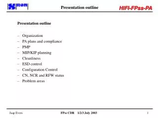
Presentation outline. Presentation outline Organization PA plans and compliance PMP MIP/KIP planning Cleanliness ESD control Configuration Control CN, NCR and RFW status Problem areas. FPss PA plans/compliance. PA plans and compliance

E N D
Presentation outline • Presentation outline • Organization • PA plans and compliance • PMP • MIP/KIP planning • Cleanliness • ESD control • Configuration Control • CN, NCR and RFW status • Problem areas FPss CDR 1/2/3 July 2003
FPss PA plans/compliance • PA plans and compliance • Instead of one overall FPss PA plan separate plans for FCU, FPU and JPL: • FCU, SRON-U/FCU/PL/2000-001 • FPU, FPSS-00026 • JPL (MU bands 5, 6L and 6H, US part), JPL D-19161 • Other FPss consortium members through compliance matrices (HIFI PA plan): • Compliance status in section 6.1 of FPSS-00026 • Sufficient agreement between members and FPss PA • All need more or less support from FPss PA to fulfil these tasks • Subcontractors PA control through SoW’s or procurement specifications FPss CDR 1/2/3 July 2003
PMP – EEE parts • EEE parts lists and procurement • All EEE parts lists established and reflecting current design status • All parts ordered at the CPPA or, if self procured, ordered at manufacturers/suppliers except Isolators • Isolator order waits finalization of PID but no delay expected • Go-ahead for housing production has been given and magnet materials procured • After approval of PID, probably shortly from now, go-ahead for production • Problems with CPPA expected delivery dates resolved for MU’s and IF amplifiers • Delivery of CPPA parts in progress and for the MU’s almost completed and for the other units expected to be on time • Parts list and procurement for IF Up-converter currently done by HIFI PA FPss CDR 1/2/3 July 2003
PMP – EEE parts – PAD status • PAD Status (28) • FPU resistors and capacitors (24 PAD’s active, 2 withdrawn) • Most of them have initial Acceptance up to HIFI System; at ESA for acceptance (19) • Some under final definition - new items like 18nF capacitor (5) • Isolators • PAD needs update: batches and sample sizes, LAT program (PAMTECH/SRON tasks), number of cold thermal cycles • IF amplifier HEMT • Under definition by HIFI System PA • CSA temperature sensor Lake Shore DT670E-BR • Initial Acceptance up to HIFI System; at ESA for acceptance • FCU OP12B • Accepted by ESA, closed FPss CDR 1/2/3 July 2003
PMP – EEE parts – PAD status • PAD’s FPU CAPACITORS AND RESISTORS • PAD’s for all capacitors and resistors because of use at cryogenic temperature • Qualification logic for these parts and applied interconnection techniques: • Parts mounted on evaluation boards of with envisaged materials and processes: • Aluminium oxide/solder/wire bond • Duroid/solder/wire bond • Duroid/conductive epoxy/wire bond • TMM/conductive epoxy/wire bond • Kapton flex print/solder • Evaluation boards cycled RT/LHe (dip stick) 100x • Destructive analysis of parts and interconnections • Boards defined, to be manufactured, cycled and evaluated, expected to be completed in October 2003 except for IF2 • JPL performs equivalent program on MU 5, 6L/6H hardware FPss CDR 1/2/3 July 2003
PMP – EEE parts – PAD status • Alcatel IF1 evaluation board • Au plated aluminium/Duroid/conductive epoxy FPss CDR 1/2/3 July 2003
PMP – EEE parts – PAD status • PAD FPU ISOLATORS • Two types of isolators that differ in outer dimensions only • PID for flight models almost completed • Two DM’s are cycled 30x at this moment; after that internal inspection and if necessary feedback into PID FM • Flight batch 100% inspection: • visual • performance at 4.2/15 Kelvin • From flight batch samples will be taken for LAT: • 2 of each type • Cycling 10x RT/LHe, 20x RT/LN2 • Extended bake out and warm cycling, 1x 144 hours at 85C + 4 cycles RT/85C • Cryogenic (80K) vibration, qualification level • Internal FPss CDR 1/2/3 July 2003
PMP – EEE parts – PAD status • PAD CSA TEMPERATURE SENSOR • Lake Shore DT670E-BR bare diode • 100% visual inspection • LAT on 4 items, 1 control item: • Mounted on alumina together with DT670SD-4L for calibration check at 4.2 and 77 K • Irradiated 10krad/Si and calibration check thereafter • Thermal cycling 353/4.2 Kelvin, 100x followed by a calibration check, visual inspection, bond pull test, die shear test. • PAD FCU OP12B • Part from XMM-RGS project • Relife and hermetic seal testing and external visual inspection performed on 25 pieces FPss CDR 1/2/3 July 2003
PMP – EEE parts – Other issues • Lake Shore Germanium thermistor GR200B • Lake Shore notified CPPA that they do not guarantee that part will survive launch vibration and does not change in calibration after bake out. • SRON performed vibration and bake out on commercially procured part • Bake out – 19 hours at 90, 145 hours at 80C • Vibration – together with console, in 11 steps from 2 upto 9 grms, 30 seconds each • No changes observed within our measuring accuracy of about 10 mKelvin • Results reported in FPSS-00402 • Proposed to CPPA to do LAT, by SRON, on 2 pieces from the FPU flight batch • Vibration at 80K, FPU qualification level • Extended bake out for 144 hours at 85C FPss CDR 1/2/3 July 2003
PMP – EEE parts – Other issues • SMA Attenuators • Radiall type R413 6xx 650, 0 – 10 dB attenuation • Located on SMA input connectors of IF2 • No documented cryogenic history available • LAT on 2 pieces from flight batches • Thermal cycling RT/LN 10x and RT/LHe 6x • Vibration at 80K, FPU qualification level FPss CDR 1/2/3 July 2003
PMP – Materials • Declared Materials Lists status • FPU – draft issue, to be updated • COA – established • DPB – in preparation • DRT – draft issue, to be updated and checked • MSA – draft issue, to be updated and checked • Console – draft issue, to be updated and checked • FPC – draft issue, to be updated and checked • CSA – draft issue, to be updated and checked • IF2 – not received yet (to be defined with selected Swiss company) • FCU – to be updated and checked • Draft issues are either based on draft or non-released production documents or on interviews FPss CDR 1/2/3 July 2003
PMP – Processes • Declared Processes Lists status • FPU – draft issue, to be updated • COA – established • DPB – in preparation • DRT – draft issue, to be updated and checked • MSA – draft issue, to be updated and checked • Console – draft issue, to be updated and checked • FPC – draft issue, to be updated and checked • CSA – draft issue, to be updated and checked • IF2 – not received yet (to be defined with selected Swiss company) • FCU – to be updated and checked • Draft issues are either based on draft or non-released production documents or on interviews FPss CDR 1/2/3 July 2003
PMP – Waveguide horns • Mixer unit waveguide horns electroforming process • Main problem with this process is fluid inclusion in corrugations, especially in the deep corrugations close to the waveguide transition • Status at RPG • RPG invested much time and in solving this problem • Optimization of electrolyte • Optimization of electroforming process • Development of an iterative process of copper growing and selective removal • Hiring a skilled and fully dedicated person for this process • Very recently they demonstrated that they were successful in producing an inclusion free MU 2 horn • No 100% guarantee that horns have no inclusions! FPss CDR 1/2/3 July 2003
PMP – Waveguide horns MU 2 horn produced with “old” process MU 2 horn produced with optimized process FPss CDR 1/2/3 July 2003
PMP – Waveguide horns Details of horn without inclusions Details of horn with inclusions FPss CDR 1/2/3 July 2003
PMP – Waveguide horns • Status at RPG, continued • PID under review by SRON and KOSMA • Before delivery, horns are thermally cycled to reveal detrimental inclusions: • 150C for one hour • 2x between RT/LN2 • Visual inspection after each test • One horn from SRON flight batch will be cut • Contents of EIDP agreed, a.o. photographs of the corrugations at three stages of the electroforming process giving some evidence of inclusion free electroforming • Status at Thomas Keating Ltd • TK is producing horns with another type of process • Status on inclusions not known yet • Same LAT as for the horns from RPG FPss CDR 1/2/3 July 2003
PMP – Riveting • Status COA riveting • HTS has riveted a COA precursor QM • External visual inspection of rivets showed that rivets are within NAS requirements • Results of micro sectioning of rivet samples were not acceptable to ETH/SRON • – probable cause is an inadequate DPA procedure of the riveting company – • HTS has produced new rivet samples that will be processed and inspected by a SRON contracted, independent, testhouse • Results expected at the end of the first week of July • If results are satisfying the go-ahead for riveting COA QM will be given • Pull strength test samples (NASM-1312-4) will be produced together with QM/FM FPss CDR 1/2/3 July 2003
PMP – Pivots • Status C-Flex pivot manufacturing • Together with SRON C-Flex has developed processes for manufacturing the pivots for the Focal Plane Chopper and Diplexers • The development was focused on: • CuBe and Inconel 718 pivots • Base material condition • Plating process CuBe • Braze and EB weld schemes • Braze materials • Hardening heat treatments • Production flow • Batches of three types were recently produced for evaluation • CuBe, 100 m spring, brazed/welded • CuBe, 130 m spring, brazed/welded • Inconel 718, 90 m spring, brazed/brazed FPss CDR 1/2/3 July 2003
PMP – Pivots • Status C-Flex pivot manufacturing, continued • Samples of all three types have been • Visually inspected • Static load tested • Vibration tested • Micro sectioned • All three types comply with the FPU requirements • Inconel 718 has been selected for use in the FPU because: • High strength • Relatively simple production flow and processes, reproducibility good • Fatigue strength acceptable • Torque rate within requirements • C-Flex PID defined and SRON procurement specification in preparation FPss CDR 1/2/3 July 2003
PMP – Semi rigid cables • Status of semi rigid cables • Two types of semi rigid cable material • Stainless steel (between 1st and 2nd Isolators) • Aluminium (all others) • Reliability problem description • Creep of PTFE dielectric due stresses induced by bending and thermal cycling could cause breakage of solder joints at SMA connector • Problem widely recognized and occurs also in cables used in the normal temperature range • References: • ECSS-Q-70-18, section 4.1 • Barry. D. Dunn; Metallurgical assessment of spacecraft parts, materials and processes; p.421 FPss CDR 1/2/3 July 2003
PMP – Semi rigid cables FPss CDR 1/2/3 July 2003
PMP – Semi rigid cables • Remedy according to specification ECSS-Q-70-18 • Thermal cycling of the cut cable between RT/-45C/RT/85C/RT • Minimum number of cycles is 3, removal of the protruding dielectric after each cycle • Mounting of the connectors only after 24 hours at RT • Evaluation performed (test report FPSS-00420) • As ECSS-Q-70-18 is meant for cables to be used in the normal temperature range different preconditioning thermal cycles schemes were applied to a range of cable types and invest their behaviour when exposed to multiple cycles between RT and LHe, LN2 and bake out temperature • It appeared that creep of dielectric in assembled cables can be detected with reflection measurements • Preconditioning of the cables by cycling 3x between RT/-45C/RT/90C/RT seems to be sufficient for cables used at cryogenic temperature • SS cable type JS50085 and aluminium type AX50085 seem to be a good choice as baseline for the semi rigid cable qualification program FPss CDR 1/2/3 July 2003
PMP – Semi rigid cables • Qualification program • Selection of cable manufacturers; two possible candidates: • SV Microwaves • Philips Natlab (R&D laboratories) • The manufacturer has to select the materials and processes and establish the manufacturing procedures according to the ECSS specification and possible amendments specified by SRON • SMA connectors are procured by SRON through the CPPA • A set of cables have to be produced according to that PID • Program • Extended bake out 144 hours at 85C and 5 cycles RT/85C • Thermal cycling 20x RT/LN2 and 10x RT/LHe • Vibration at 80K, FPU qualification level • Reflection measurements • DPA on connector samples to verify solder quality FPss CDR 1/2/3 July 2003
PMP – Polarizing grids • Polarizing grids • Manufactured by QMC on SRON manufactured frames • Frame material Sanmac SS 304L frames • Mylar thickness 1.5 m • Grid material sputtered copper, photographically patterned • Copper thickness 0.4 m • Photoresist Microposit 1805 for copper protection • Mylar glued between two frames with Torr Seal • Evaluation performed on DM grids • Cold cycling had no effect on flatness, tensile stress loss of about 30% • Bake out no effect on flatness and a tensile stress loss of about 20% • Remaining tensile stress sufficient • Vibration at 80K did not show any effect on grids • Sufficient flatness for visible light alignment • Test report FPSS-00012 FPss CDR 1/2/3 July 2003
PMP – Polarizing grids • Grid LAT program on flight batch • 100% visual inspection • 100% grid pitch and width • 100% flatness • Two samples from flight batch for: • Extended bake out 144 hours at 85C and 5 cycles RT/85C • Thermal cycling 20x RT/LN2 and 10x RT/LHe FPss CDR 1/2/3 July 2003
PMP – Absorbing coating • Absorbing coating • Stycast 2850FT/24LV mixed with SiC grains (volume ratio – 3:1, weight ratio – 1:1) • Outgassing properties Stycast 2850FT/24LV (source: GSC outgassing data base) • TML – 0.5% - 1%, mean 0.6 • CVCM – 0.01% - 0.18%, mean 0.04% • Coating mass – 0.18 g/cm2 of which 0.9 g/cm2 Stycast • Total area of coating in FPU – 2520 cm2 • Total coating mass in FPU – 454 grams of which 227 grams Stycast • Estimated TML – 1.4 grams mean, 2.3 grams max • Estimated CVCM – 0.1 grams mean, 0.41 grams max • Outgassing properties of the absorbing coating may differ because of the large exposed surface area, variation in Stycast production lots, applied cure scheme • Outgassing properties will be verified in the near future FPss CDR 1/2/3 July 2003
MIP/KIP planning • MIP/KIP • MIP’s currently not foreseen • KIP’s FPU and subunits thereof defined in FPss-00309 • COA, after machining mechanical parts and riveting • MU’s (except MU’s 5 and 6L/H, is JPL task) electrical boards before integration and internal electrical connections • IF amplifiers before closing boxes • CSA Warm source after assembly • FPC pivot manufacturing, before and after pivot integration, LVDT’s and Actuators, before closing • DRT’s before and after pivot integration, before closing Actuator • MSA’s before closing boxes • Consoles after full assembly • Grids before integration • KIP’s FCU and parts thereof planned in FCU PA plan, SRON-U/FCU/PL/2000-001 • Each board before conformal coating • After full assembly FPss CDR 1/2/3 July 2003
Cleanliness control • Cleanliness Requirements • FPU • Particles – 300 ppm • Molecular– 4.10E-6 g/cm2 • FCU • Particles – 300 ppm • Control • One overall HIFI cleanliness control plan in cooperation with Subsystems down to the lowest level, no lower level control plans (SRON-U/HIFI/PL/2001-002) • Recording of exposure times to the different environment • On FPss level clean rooms and benches are validated to FED-STD-209 by an external company every year • Particle counter for on line monitoring in clean room • Molecular contamination monitoring periodically • Clean room garments – ESD safe – are regularly cleaned, dependent on use FPss CDR 1/2/3 July 2003
Cleanliness control • Facilities • Available clean areas for FPU assembly and handling (requirement – class 1,000): • Clean room class 100 • Clean benches class 100 • Clean tent class TBD • Available clean areas for FCU assembly and handling (requirement – class 100,000): • Clean room class 100.000 • For FPU subunits clean benches and clean rooms of class <1000 available at the FPU consortium institutes and subcontractors • Clean room and facility monitoring • On FPss level clean rooms and benches are validated to FED-STD-209 by an external company every year • Initial determination of the molecular contamination potential during QM program of: • Clean room, clean benches • SRON MSA cryostat • CTH MSA cryostat (beam measurements) • FPU cryostat FPss CDR 1/2/3 July 2003
Cleanliness control FPss CDR 1/2/3 July 2003
ESD control • ESD plan SRON-G/FPU/PL/2001-001(FPSS-00183), issue2 • Four levels of ESD safe areas defined: • SIS/HEB/HEMT devices < 20V • MU’s/IF amplifiers/FPU/LOU < 100V • FCU/LSU/LCU < 1000V • Non ESD sensitivity hardware • (Sub)unit sensitivities in ESD plan are still estimates • (Sub)unit suppliers have to communicate sensitivities to the FPss; required for final classification and definition of protective measures • Integration/assembly/test locations and ESD measures for ESD sensitive hardware are defined with present sensitivity estimates as in ESD plan • ESD safe work locations available for all levels of ESD sensitivity, including for SIS, HEB and HEMT devices. • Guidelines for assembly and cable hook up FPss CDR 1/2/3 July 2003
ESD control • Facilities evaluation and personnel training • Facilities evaluated by a JPL expert and found acceptable with minor recommendations. Recommendations are implemented. • Personnel at institutes and subcontractors, receiving US ESD sensitive hardware, were trained by JPL expert. All passed the exam FPss CDR 1/2/3 July 2003
Configuration Control • Organization • Configuration Control performed at location of design responsible institute • FCU – SRON-U • FPU – SRON-G • DA, DRT, FPC, MSA’s – SRON-G • CSA – SRON-U • IF1L/H – YEBES/Alcatel • IF2 – ETH/Swiss industry • MU’s – MU institutes • Upconverter – TBD FPss CDR 1/2/3 July 2003
Configuration Control – CIDL/PID FPss CDR 1/2/3 July 2003
Configuration Control – CIDL/PID • Configuration Item Data List status • FCU – in DM phase; CIDL FM to be made soon • FPU QM – in preparation • COA QM – requirements and production documents part established • DA QM – production documents part established • DA FM – production documents part almost ready • DRT QM – production documents part established • MSA3V QM and FM – production documents part almost ready • MSA3H QM and FM – production documents part almost ready • FPss GSE’s – in preparation • CIDL’s of other subunits still have to be made • Process Identification Document status • MU’s and IF1H – almost established • IF1L – to be made but most of the contents the same as for IF1H • IF2 modules – to be made by to be selected Swiss industry FPss CDR 1/2/3 July 2003
Configuration Control - CSL • Configuration Status • Change Notes • Total of 13 CN’s • 11 for FPU, 4 closed, status of some unclear or at least open • 2 for FCU, both closed • Main changes • Band 7 deleted • HEB change in band 6H • IF frequency change and Upconverter added • FPU mechanical interface with Optical Bench • FPC DM – QM/FM design change Problems • FPss Change register not well maintained • Insufficient communication and coordination between FPss CC and HIFI CC FPss CDR 1/2/3 July 2003
Configuration Control - CSL • Requests for Waiver • 3 RFW’s for COA QM issued by the manufacturer, all closed, all level 4 • Two accepted – corner radii of COA parts • One rejected – Alodine 1500 instead of 1000 • NonConformance Reports • Total of 12 NCR’s. 1 open, 10 closed, 11 level 4, 1 level 2 • DRT QM • 1 NCR, level 4, open • Lack of Configuration Control, corrected • FPU mirrors • 2 NCR’s, level 4, closed • Insufficient production specification, corrected FPss CDR 1/2/3 July 2003
Configuration Control - CSL • NonConformance Reports, continued • COA QM • 8 NCR’s, level 4, all closed • Mechanical parts production errors, some remanufactured, others acceptable and closed out as use as is • InP HEMT • One NCR, level 2 (processed by JPL/HIFI), open • Used in IF1L, IF1H and IF2 • Transistors from flight lot iher 1az1 wafer 4200-071 performed poor in test amplifier • Bad performance confirmed in IF1 and IF2 amplifiers • Some of the effects: • Higher noise (not good enough for bands 5 and 6) IF1 • Either worse input matching or gain of IF2 FPss CDR 1/2/3 July 2003
Problems • Main problem • Evaluation, LAT and qualification programs • The evaluation, LAT and qualification programs to prevent parts and subunits with low quality and reliability being built into the FM cannot be done in a timely manner. • Hardly any or no feedback from these programs into the flight (sub)units • Possible solutions • More manpower and/or time • Limit the programs to an agreed and acceptable risk • Prioritize the items and accept the late completion of the last items FPss CDR 1/2/3 July 2003