Download
1 / 45
450 likes | 646 Views
Embedded Computing. Three key embedded system technologies. Technology A manner of accomplishing a task, especially using technical processes, methods, or knowledge Three key technologies for embedded systems Processor technology IC technology Design technology. Processor Technology.

E N D
Three key embedded system technologies • Technology • A manner of accomplishing a task, especially using technical processes, methods, or knowledge • Three key technologies for embedded systems • Processor technology • IC technology • Design technology
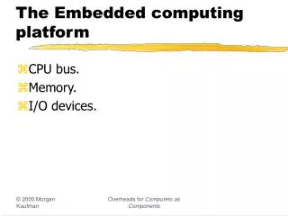
Processor technology • The architecture of the computation engine used to implement a system’s desired functionality • Processor does not have to be programmable • “Processor”not equal to general-purpose processor Controller Datapath Controller Datapath Controller Datapath Control logic index Control logic and State register Control logic and State register Registers Register file total Custom ALU State register + General ALU IR PC IR PC Data memory Data memory Program memory Data memory Program memory Assembly code for: total = 0 for i =1 to … Assembly code for: total = 0 for i =1 to … General-purpose(“software”) Application-specific Single-purpose(“hardware”)
Processor technology • Processors vary in their customization for the problem at hand total = 0 for i = 1 to N loop total += M[i] end loop Desired functionality General-purpose processor Application-specific processor Single-purpose processor
Controller Datapath Control logic and State register Register file General ALU IR PC Program memory Data memory Assembly code for: total = 0 for i =1 to … General-purpose processors • Programmable device used in a variety of applications • Also known as “microprocessor” • Features • Program memory • General datapath with large register file and general ALU • User benefits • Low time-to-market and NRE costs • High flexibility • “Pentium” the most well-known, but there are hundreds of others
Datapath Controller Control logic index total State register + Data memory Single-purpose processors • Digital circuit designed to execute exactly one program • a.k.a. coprocessor, accelerator or peripheral • Features • Contains only the components needed to execute a single program • No program memory • Benefits • Fast • Low power • Small size
Application-specific processors • Programmable processor optimized for a particular class of applications having common characteristics • Compromise between general-purpose and single-purpose processors • Features • Program memory • Optimized datapath • Special functional units • Benefits • Some flexibility, good performance, size and power Controller Datapath Control logic and State register Registers Custom ALU IR PC Data memory Program memory Assembly code for: total = 0 for i =1 to …
gate oxide IC package IC source channel drain Silicon substrate IC technology • The manner in which a digital (gate-level) implementation is mapped onto an IC • IC: Integrated circuit, or “chip” • IC technologies differ in their customization to a design • IC’s consist of numerous layers (perhaps 10 or more) • IC technologies differ with respect to who builds each layer and when
IC technology • Three types of IC technologies • Full-custom/VLSI • Semi-custom ASIC (gate array and standard cell) • PLD (Programmable Logic Device)
Outline • Anatomy of integrated circuits • Full-Custom (VLSI) IC Technology • Semi-Custom (ASIC) IC Technology • Programmable Logic Device (PLD) IC Technology
CMOS transistor • Source, Drain • Diffusion area where electrons can flow • Can be connected to metal contacts (via’s) • Gate • Polysilicon area where control voltage is applied • Oxide • Si O2 Insulator so the gate voltage can’t leak
gate oxide IC package IC source channel drain Silicon substrate End of the Moore’s Law? • Moore’s Law • Chip density – doubling the number of transistors on a chip every 1.5 to 2 years • Every dimension of the MOSFET has to scale • (PMOS) Gate oxide has to scale down to • Increase gate capacitance • Reduce leakage current from S to D • Current gate oxide thickness is about 2.5-3nm • That’s about 25 atoms!!!
SiO2 산화막(약 0.6 micron) P type silicon gate oxide(약 0.05 micron) AS이온 주입 Source, drain 영역 형성 n+ n+ NMOS Inverter NMOS Transistor(NMOS FET) polysilicon(Low Pressure Chemical Vapor Deposition 으로 얹음)
산화막 성장 n+ n+ n+ n+ 2l l NMOS Inverter contact 부분 식각후 aluminum 증착, 패턴 형성 Length unit --- l (micron)
NAND • Metal layers for routing (~10) • PMOS don’t like 0 • NMOS don’t like 1 • A stick diagram form the basis for mask sets
Silicon manufacturing steps • Tape out • Send design to manufacturing • Spin • One time through the manufacturing process • Photolithography • Drawing patterns by using photo-resist to form barriers for deposition
Full Custom • All layers are optimized for an embedded system’s particular digital implementation • Placing transistors • Place and orient transistors • Sizing transistors • Make fat, fast wires or thin, slow wires • May also need to size buffer • Routing wires • Connect transistors • Benefits • Excellent performance, small size, low power • Drawbacks • High NRE cost (e.g., $300k), long time-to-market • Very Large Scale Integration (VLSI)
Full Custom • Best size, power, performance • Hand design • Horrible time-to-market/flexibility/NRE cost… • Reserve for the most important units in a processor • ALU, Instruction fetch… • Physical design tools • Less optimal, but faster…
Semi-custom • Lower layers are fully or partially built • Designers are left with routing of wires and maybe placing some blocks • Benefits • Good performance, good size, less NRE cost than a full-custom implementation (perhaps $10k to $100k) • Drawbacks • Still require weeks to months to develop
Semi-Custom • Gate Array • Array of prefabricated gates • “place” and route • Higher density, faster time-to-market • Does not integrate as well with full-custom • Standard Cell • A library of pre-designed cell • Place and route • Lower density, higher complexity • Integrate great with full-custom • Structured ASIC
Semi-Custom • Most popular design style • Jack of all trade • Good • Power, time-to-market, performance, NRE cost, per-unit cost, area… • Master of none • Integrate with full custom for critical regions of design
PLD (Programmable Logic Device) • All layers already exist • Designers can purchase an IC • Connections on the IC are either created or destroyed to implement desired functionality • Field-Programmable Gate Array (FPGA) very popular • Benefits • Low NRE costs, • Almost instant IC availability • Drawbacks • Bigger • High unit cost, bad for large volume • expensive (perhaps $30 per unit) • Power hungry • Except special PLA • Slower
Programmable Logic Device • Programmable Logic Device • Programmable Logic Array (PLA), • Programmable Array Logic (PAL), • Field Programmable Gate Array (FPGA) 1600 usable gate, 7.5 ns $7 list price
x x x 1 2 n Input buffers and inverters x x x x 1 n 1 n P 1 OR plane AND plane P k f f m 1 Programmable Logic Array (PLA) • Pre-fabricated building block of many AND/OR gates • “personalized” by making or breaking connections among the gates • Programmable array block diagram for sum of products form
x x x 1 2 3 Programmable connections OR plane P 1 P 2 P 3 P 4 AND plane f f 1 2 Gate-level Diagram of a PLA f1 and f2 ??
x x x 1 2 3 P 1 f 1 P 2 P 3 f 2 P 4 AND plane Programmable Array Logic (PAL)
Field-Programmable Gate Arrays (FPGAs) • FPGAs are programmable devices that support relatively large circuits • Macrocell of PLDs : 20 gates • PAL : 8 macrocell (160 gates) • CPLD : 500 macrocell (10,000 gates) • Different from CPLDs since they do not contain AND and OR planes • Provide logic blocks for implementing the logic functions • Three main types of resources • Logic blocks • I/O blocks • Interconnection wires
General-purpose processor ASIP Single- purpose processor General, providing improved: Customized, providing improved: Flexibility Maintainability NRE cost Time- to-prototype Time-to-market Cost (low volume) Power efficiency Performance Size Cost (high volume) PLD Semi-custom Full-custom Independence of processor and IC technologies • Basic tradeoff • General vs. custom • With respect to processor technology or IC technology • The two technologies are independent
10,000 1,000 100 Logic transistors per chip (in millions) 10 1 0.1 0.01 0.001 1981 1983 1985 1987 1989 1991 1993 1995 1997 1999 2001 2003 2005 2007 2009 Moore’s law • The most important trend in embedded systems • Predicted in 1965 by Intel co-founder Gordon Moore IC transistor capacity has doubled roughly every 18 months for the past several decades Note: logarithmic scale
Graphical illustration of Moore’s law • Something that doubles frequently grows more quickly than most people realize! • A 2002 chip can hold about 15,000 1981 chips inside itself 1981 1984 1987 1990 1993 1996 1999 2002 10,000 transistors 150,000,000 transistors Leading edge chip in 1981 Leading edge chip in 2002
Compilation/ Synthesis Libraries/ IP Test/ Verification System specification System synthesis Hw/Sw/ OS Model simulat./ checkers Compilation/Synthesis: Automates exploration and insertion of implementation details for lower level. Behavioral specification Behavior synthesis Cores Hw-Sw cosimulators Libraries/IP: Incorporates pre-designed implementation from lower abstraction level into higher level. RT specification RT synthesis RT components HDL simulators Test/Verification: Ensures correct functionality at each level, thus reducing costly iterations between levels. Logic specification Logic synthesis Gates/ Cells Gate simulators To final implementation Design Technology • The manner in which we convert our concept of desired system functionality into an implementation
Design productivity exponential increase • Exponential increase over the past few decades 100,000 10,000 1,000 100 Productivity (K) Trans./Staff – Mo. 10 1 0.1 0.01 1981 2009 1995 2007 1997 1993 1989 1999 2001 1991 1983 2003 1987 1985 2005
10,000 100,000 1,000 10,000 100 1000 Logic transistors per chip (in millions) Gap Productivity (K) Trans./Staff-Mo. 10 100 IC capacity 1 10 0.1 1 productivity 0.01 0.1 0.001 0.01 1981 1983 1985 1987 1989 1991 1993 1995 1997 1999 2001 2003 2005 2007 2009 Design productivity gap • While designer productivity has grown at an impressive rate over the past decades, the rate of improvement has not kept pace with chip capacity
10,000 100,000 1,000 10,000 100 1000 Logic transistors per chip (in millions) Gap Productivity (K) Trans./Staff-Mo. 10 100 IC capacity 1 10 0.1 1 productivity 0.01 0.1 0.001 0.01 1981 1983 1985 1987 1989 1991 1993 1995 1997 1999 2001 2003 2005 2007 2009 Design productivity gap • 1981 leading edge chip required 100 designer months • 10,000 transistors / 100 transistors/month • 2002 leading edge chip requires 30,000 designer months • 150,000,000 / 5000 transistors/month • Designer cost increase from $1M to $300M
Team 15 60000 16 16 18 50000 19 40000 23 24 30000 Months until completion 20000 43 Individual 10000 0 10 20 30 40 Number of designers The mythical man-month • The situation is even worse than the productivity gap indicates • In theory, adding designers to team reduces project completion time • In reality, productivity per designer decreases due to complexities of team management and communication • In the software community, known as “the mythical man-month” (Brooks 1975) • At some point, can actually lengthen project completion time! (“Too many cooks”) • 1M transistors, 1 designer =5000 trans/month • Each additional designer reduces for 100 trans/month • So 2 designers produce 4900 trans/month each
Specification Automation Verification Reuse Implementation Improving productivity • Design technologies developed to improve productivity • We focus on technologies advancing hardware/software unified view • Automation • Program replaces manual design • Synthesis • Reuse • Predesigned components • Cores • General-purpose and single-purpose processors on single IC • Verification • Ensuring correctness/completeness of each design step • Hardware/software co-simulation
Summary • Embedded systems are everywhere • Key challenge: optimization of design metrics • Design metrics compete with one another • A unified view of hardware and software is necessary to improve productivity • Three key technologies • Processor: general-purpose, application-specific, single-purpose • IC: Full-custom, semi-custom, PLD • Design: Compilation/synthesis, libraries/IP, test/verification