Download
1 / 39
390 likes | 502 Views
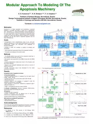
This chapter introduces the evolution of hardware design, highlighting the dramatic shift towards using computer-aided design tools and abstract representations. It explores the transformation of hardware design methodologies, now resembling software design practices, and the importance of sound design methodologies in achieving efficient and reliable systems. Key topics include functional specifications, performance constraints, and rapid prototyping technologies. The chapter emphasizes the need for precise representation and effective debugging strategies to facilitate the design process of modern digital systems.

E N D
Chapter # 1: IntroductionContemporary Logic DesignRandy H. KatzUniversity of California, BerkeleyCSIE, NCTUSep. 1999
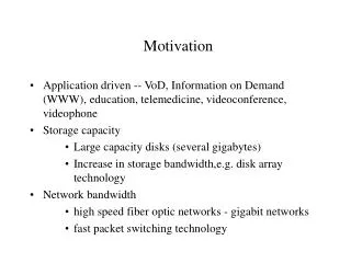
Motivation Dramatic Change in the Way Industry Does Hardware Design Pervasive use of Computer-Aided Design Tools Deemphasis on hand design methods Emphasis on abstract design representations Hardware design begins to look like software design Emergence of Rapid Implementation Circuit Technology Programmable rather than discrete logic Importance of Sound Design Methodologies Synchronous Designs Rules of Composition
The Elements of Modern Design Representations, Circuit Technologies, Rapid Prototyping Design Representations Behaviors Blocks Waveforms Gates Truth Tables Boolean Algebra Switches Rapid Prototyping Technologies Simulation Synthesis PAL, PLA, ROM, PLD MOS Computer-Aided Design TTL Circuit Technologies
Chapter Overview Process of Design Digital Systems Design Representations Rapid Prototyping
The Process Of Design Design Initial concept: what is the function performed by the object? Constraints: How fast? How much area? How much cost? Refine abstract functional blocks into more concrete realizations Implementation Assemble primitives into more complex building blocks Composition via wiring Choose among alternatives to improve the design Debug Faulty systems: design flaws, composition flaws, component flaws Design to make debugging easier Hypothesis formation and troubleshooting skills
The Art Of Design: Refinement of Representations 1. Functional Specification/What the System Does Ex: Traffic Light Controller Lights point in the directions N, S, E, W Illuminates the same lights N as S and E as W Cycles thru the sequence GREEN-YELLOW-RED N-S and E-W never GREEN or YELLOW at the same time Stay GREEN for 45 seconds, yellow for 15, red for 60 2. Performance Constraints/Requirements to be Met speed: compute changes in under 100 ms power: consume less than 20 watts area: implementation in less than 20 square cm cost: less than $20 in manufacturing costs
The Art of Design: "To Design Is To Represent" 1. English language specification easy to write, but not precise and subject to ambiguity 2. Functional description more precise specification flow charts, program fragments 3. Structural description complex components decomposed into compositions of less complex components 4. Physical description the design in terms of most primitive building blocks, e. g., logic gates or transistors
The Process of Design Implementation as Assembly Top Down Design: Complex functions replaced by more primitive functions Bottom Up Design: Primitives composed to build more and more complex assemblies Rules of Composition and Correctness by Construction: Electrical Rules: how many components can be cascaded? Timing Rules: how does the system change in conjunction with periodic triggering events?
The Process of Design Top Down Decomposition Structural Representation To decomposition of high level functions into more primitive functions
The Process of Design Bottom Up Assembly Building Primitives composed to build more and more complex assemblies e.g., a group of rooms form a floor e.g., a group of floors form a bldg. a group of transistors form a gate a group of gates form an addition circuit addition circuits plus storage circuits form a processor datapath Floor Rooms
Digital Hardware Systems Digital Systems Digital vs. Analog Waveforms Digital: only assumes discrete values Analog: values vary over a broad range continuously
Digital Hardware Systems Advantages of Digital Systems Analog systems: slight error in input yields large error in output Digital systems more accurate and reliable Readily available as self-contained, easy to cascade building blocks Computers use digital circuits internally Interface circuits (i.e., sensors & actuators) often analog This course is about logic design, not system design (processor architecture), not circuit design (transistor level)
Digital Hardware Systems Digital Binary Systems Two discrete values: yes, on, 5 volts, current flowing, magnetized North, "1" no, off, 0 volts, no current flowing, magnetized South, "0" Advantage of binary systems: rigorous mathematical foundation based on logic both the door must be open and the car running before I can back out IF the garage door is open AND the car is running THEN the car can be backed out of the garage IF N-S is green AND E-W is red AND 45 seconds has expired since the last light change THEN we can advance to the next light configuration the three preconditions must be true to imply the conclusion
Digital Hardware Systems Boolean Algebra and Logical Operators Algebra: variables, values, operations In Boolean algebra, the values are the symbols 0 and 1 If a logic statement is false, it has value 0 If a logic statement is true, it has value 1 Operations: AND, OR, NOT
Digital Hardware Systems Hardware Systems and Logical Operators IF the garage door is open AND the car is running THEN the car can be backed out of the garage door open? car running? back out car? false/0 true/1 false/0 true/1 false/0 false/0 false/0 TRUE/1 false/0 false/0 true/1 true/1
Digital Hardware Systems The Real World Physical electronic components are continuous, not discrete! These are the building blocks of all digital components! Transition from logic 1 to logic 0 does not take place instantaneously in real digital systems Intermediate values may be visible for an instant Boolean algebra useful for describing the steady state behavior of digital systems Be aware of the dynamic, time varying behavior too!
Digital Hardware Systems Digital Circuit Technologies Integrated circuit technology choice of conducting, non-conducting, sometimes conducting ("semiconductor") materials whether or not their interaction allows electrons to flow forms the basis for electrically controlled switches Main technologies MOS: Metal-Oxide-Silicon Bipolar Transistor-Transistor Logic Emitter Coupled Logic
Digital Hardware Systems MOS Technology Transistor basic electrical switch three terminal switch: gate, source, drain voltage between gate and source exceeds threshold switch is conducting or "closed" electrons flow between source and drain when voltage is removed, the switch is "open" or non-conducting connection between source and drain is broken
Digital Hardware Systems Circuit that implements logical negation (NOT) 1 at input yields 0 at output 0 at input yields 1 at output Inverter behavior as a function of input voltage input ramps from 0V to 5V output holds at 5V for some range of small input voltages then changes rapidly, but not instantaneously! remember distinction between steady state and dynamic behavior
Digital Hardware Systems Combinational vs. Sequential Logic Network implemented from switching elements or logic gates. The presence of feedback distinguishes between sequential and combinational networks. Combinational logic no feedback among inputs and outputs outputs are a pure function of the inputs e.g., full adder circuit: (A, B, Carry In) mapped into (Sum, Carry Out)
Digital Hardware Systems Sequential logic inputs and outputs overlap outputs depend on inputs and the entire history of execution! network typically has only a limited number of unique configurations these are called states e.g., traffic light controller sequences infinitely through four states new component in sequential logic networks: storage elements to remember the current state output and new state is a function of the inputs and the old state i.e., the fed back inputs are the state! Synchronous systems period reference signal, the clock, causes the storage elements to accept new values and to change state Asynchronous systems no single indication of when to change state
Digital Hardware Systems Combinational vs Sequential Logic Traffic Light Example Next State Logic Current State Output Logic Maps current state and alarm events into the next state Storage elements replaced by next state when the clock signal arrives Current state mapped into control signals to change the lights and to start the event timers IF controller in state N-S green, E-W red AND the 45 second timer alarm is asserted THEN the next state becomes N-S yellow, E-W red when the clk signal is next asserted
Representations of a Digital Design Switches A switch connects two points under control signal. when the control signal is 0 (false), the switch is open when it is 1 (true), the switch is closed Normally Open Normally Closed when control is 1 (true), switch is open when control is 0 (false), switch is closed
Representations of a Digital Design: Switches Examples: routing inputs to outputs through a maze Floating nodes: what happens if the car is not running? outputs are floating rather than forced to be false Under all possible control signal settings (1) all outputs must be connected to some input through a path (2) no output is connected to more than one input through any path
Representations of a Digital Design: Switches Implementation of AND and OR Functions with Switches AND function Series connection to TRUE OR function Parallel connection to TRUE
Representations of a Digital Design Truth Tables tabulate all possible input combinations and their associated output values Example: half adder adds two binary digits to form Sum and Carry Example: full adder adds two binary digits and Carry in to form Sum and Carry Out NOTE: 1 plus 1 is 0 with a carry of 1 in binary
Representations of a Digital Design Boolean Algebra values: 0, 1 variables: A, B, C, . . ., X, Y, Z operations: NOT, AND, OR, . . . NOT X is written as X X AND Y is written as X & Y, or sometimes X Y X OR Y is written as X + Y Deriving Boolean equations from truth tables: Sum = A B + A B Carry 0 0 0 1 A 0 0 1 1 B 0 1 0 1 Sum 0 1 1 0 OR'd together product terms for each truth table row where the function is 1 if input variable is 0, it appears in complemented form; if 1, it appears uncomplemented Carry = A B
Representations of a Digital Design: Boolean Algebra Another example: Sum = A B Cin + A B Cin + A B Cin + A B Cin Sum 0 1 1 0 1 0 0 1 Cout 0 0 0 1 0 1 1 1 A 0 0 0 0 1 1 1 1 B 0 0 1 1 0 0 1 1 Cin 0 1 0 1 0 1 0 1 Cout = A B Cin + A B Cin + A B Cin + A B Cin
Representations of a Digital Design: Boolean Algebra Reducing the complexity of Boolean equations Laws of Boolean algebra can be applied to full adder's carry out function to derive the following simplified expression: Cout = A Cin + B Cin + A B Verify equivalence with the original Carry Out truth table: place a 1 in each truth table row where the product term is true each product term in the above equation covers exactly two rows in the truth table; several rows are "covered" by more than one term
Representations of a Digital Design Gates most widely used primitive building block in digital system design Standard Logic Gate Representation Half Adder Schematic Net: electrically connected collection of wires Netlist: tabulation of gate inputs & outputs and the nets they are connected to
Representations of a Digital Design: Gates Full Adder Schematic Fan-in: number of inputs to a gate Fan-out: number of gate inputs an output is connected to Technology "Rules of Composition" place limits on fan-in/fan-out
Representations of a Digital Design Waveforms dynamic behavior of a circuit real circuits have non-zero delays Timing Diagram of the Half Adder sum propagation delay sum propagation delay circuit hazard: 1 plus 0 is 1, not 0! Output changes are delayed from input changes The propagation delay is sensitive to paths in the circuit Outputs may temporarily change from the correct value to the wrong value back again to the correct value: this is called a glitch or hazard
Representations of a Digital Design: Waveforms 10 time units of delay Tracing the Delays: A=0,B=0 to A=0,B=1 (i) Initial conditions (ii) Y changes from 0 to 1 (iv) Output of OR gate changes after 10 time units (iii) Output of top AND gate changes after 10 time units
Representations of a Digital Design Blocks structural organization of the design black boxes with input and output connections corresponds to well defined functions concentrates on how the components are composed by wiring Block diagram representation of the Full Adder Full Adder realized in terms of composition of half adder blocks
Representations of a Digital Design Waveform Verification Does the composed full adder behave the same as the full gate implementation? Sum, Cout waveforms lag input changes in time How many time units after input change is it safe to examine the outputs?
MODULE half_adder; a, b, sum, carry PIN 1, 2, 3, 4; TRUTH_TABLE {[a, b] -> [sum, carry]} [0, 0] -> [0, 0]; [0, 1] -> [1, 0]; [1, 0] -> [1, 0]; [1, 1] -> [0, 1]; END half_adder; Representation of a Digital Design: Behaviors ABEL Hardware Description Language Truth Table Specification MODULE half_adder; a, b, sum, carry PIN 1, 2, 3, 4; EQUATIONS SUM = (A & !B) # (!A & B); CARRY = A & B; END half_adder; Equation Specification NOT AND OR
Representations of a Digital Design Behaviors Hardware description languages structure and function of the digital design Example: Half Adder in Verilog Black Box View as seen by outside world module half_adder (sum, carry, a, b) ; output sum, carry ; input a, b ; assign sum = (~a&b)|(a&~b) ; assign carry = a & b ; endmodule Internal Behavior
Representation of a Digital Design: Behaviors Black Box View as seen by outside world module half_adder (sum, carry, a, b) ; output sum, carry ; input a, b ; not #5 i1 (s1, a) ; not #5 I2 (s2, b) ; and #10 a1 (s3, b, s1) ; and #10 a2 (s4, a, s2) ; or #10 o1 (sum, s3, s4) ; and #10 a3 (carry, a, b) ; endmodule Textual description of the netlist Note delay statement This Verilog specification corresponds to the following labeled schematic
Chapter Review We have introduced: the process of design: functional decomposition and design by assembly the kinds of systems we will be designing: combinational and sequential logic binary digital systems implemented in MOS and bipolar technology the many levels of design representation: from switches to behavioral descriptions