Chapter 5 The Discontinuous Conduction Mode
560 likes | 887 Views
Chapter 5 The Discontinuous Conduction Mode. 5 The Discontinuous Conduction Mode. 5 The Discontinuous Conduction Mode.

Chapter 5 The Discontinuous Conduction Mode
E N D
Presentation Transcript
Chapter 5 The Discontinuous Conduction Mode
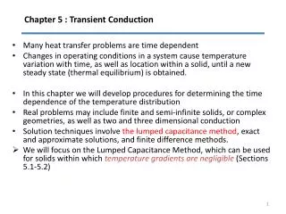
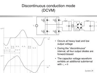
5 The Discontinuous Conduction Mode When the ideal switches of a dc-dc converter are implemented using current-unidirectional and/or voltage-unidirectional semiconductor switches, one or more new modes of operation known as discontinuous conduction modes (DCM) can occur. The discontinuous conduction mode arises when the switching ripple in an inductor current or capacitor voltage is large enough to cause the polarity of the applied switch current or voltage to reverse, such that the current- or voltage-unidirectional assumptions made in realizing the switch with semiconductor devices are violated. The DCM is commonly observed in dc–dc converters and rectifiers, and can also sometimes occur in inverters or in other converters containing two quadrant switches.
5 The Discontinuous Conduction Mode The discontinuous conduction mode typically occurs with large inductor current ripple in a converter operating at light load(small load current) and containing current-unidirectional switches. Since it is usually required that converters operate with their loads removed, DCM is frequently encountered. Indeed, some converters are purposely designed to operate in DCM for all loads. The properties of converters change radically in the discontinuous conduction mode. The conversion ratio M becomes load-dependent, and the output impedance is increased. Control of the output may be lost when the load is removed. We will see in a later chapter that the converter dynamics are also significantly altered.
5 The Discontinuous Conduction Mode The principles of inductor volt-second balance and capacitor charge balance must always be true in steady state, regardless of the operating mode. However, application of the small ripple approximation requires some care, since the inductor current ripple (or one of the inductor current or capacitor voltage ripples) is not small. Buck and boost converters are solved as examples. Characteristics of the basic buck, boost, and buck-boost converters are summarized in tabular form.(表格形式)
5.1. Origin of the discontinuous conduction mode, and mode boundary
5.1. Origin of the discontinuous conduction mode, and mode boundary As described in Chapter 2,the inductor current waveform contains a dc component I, plus switching ripple of peak amplitude . During the second subinterval, the diode current is identical to the inductor current. The minimum diode current during the second subinterval is equal to . since the diode is a single-quadrant switch, operation in the continuous conduction mode requires that this current remain positive. As shown in Chapter 2, the inductor current dc component I is equal to the load current:
5.1. Origin of the discontinuous conduction mode, and mode boundary since no dc current flows through capacitor C. It can be seen that I depends on the load resistance R. Theswitching ripple peak amplitude is: The ripple magnitude depends on the applied voltage , on the inductance L, and on the transistor conduction time . But it does not depend on the load resistance R. The inductor current ripple magnitude varies with the applied voltages rather than the applied currents.
5.1. Origin of the discontinuous conduction mode, and mode boundary Suppose now that the load resistance R is increased, so that the dc load current is decreased. The dc component of inductor current I will then decrease, but the ripple magnitude will remain unchanged. If we continue to increase R, eventually the point is reached where , illustrated in Fig.5.3. It can be seen that the inductor current and the diode current are both zero at the end of the switching period. Yet the load current is positive and nonzero.
5.1. Origin of the discontinuous conduction mode, and mode boundary
5.1. Origin of the discontinuous conduction mode, and mode boundary What happens if we continue to increase the load resistance R? The diode current cannot be negative; therefore, the diode must become reverse-biased before the end of the switching period. As illustrated in Fig. 5.4, there are now three subintervals during each switching period . During the first subinterval of length , the transistor conducts, and the diode conducts during the second subinterval of length . At the end of the second subinterval the diode current reaches zero, and for the remainder of the switching period neither the transistor nor the diode conduct. The converter operates in the discontinuous conduction mode.
5.1. Origin of the discontinuous conduction mode, and mode boundary
5.1. Origin of the discontinuous conduction mode, and mode boundary Mode boundary Insert buck converter expression for I and Simplify This expression is of the form
5.1. Origin of the discontinuous conduction mode, and mode boundary The dimensionless parameter K is a measure of the tendency of a converter to operate in the discontinuous conduction mode. Large values of K lead to continuous mode operation, while small values lead to the discontinuous mode for some values of duty cycle. The critical value(临界值) of K at the boundary between modes, is a function of duty cycle, and is equal to for the buck converter.
5.1. Origin of the discontinuous conduction mode, and mode boundary K and Kcritvs. D
5.1. Origin of the discontinuous conduction mode, and mode boundary It is natural to express the mode boundary in terms of the load resistance R, rather than the dimensionless parameter K. Equation (5.6) can be rearranged to directly expose the dependence of the mode boundary on the load resistance: Critical load resistance Rcrit Solve Kcrit equation for load resisitance R: For CCM For DCM
5.1. Origin of the discontinuous conduction mode, and mode boundary Summary: mode boundary
5.2. Analysis of the conversion ratio M(D,K) With a few modifications, the same techniques and approximations developed in Chapter 2 for the steady-state analysis of the continuous conduction mode may be applied to the discontinuous conduction mode. Analysis techniques for the discontinuous conduction mode: Inductor volt-second balance Capacitor charge balance
5.2. Analysis of the conversion ratio M(D,K) Small ripple approximation sometimes applies: because is a poor approximation when Converter steady-state equations obtained via charge balance on each capacitor and volt-second balance on each inductor. Use care in applying small ripple approximation.
5.2. Analysis of the conversion ratio M(D,K) Output capacitor voltage ripple. Regardless of the operating mode, it is required that the output voltage ripple be small. Hence, for a well-designed converter operating in the discontinuous conduction mode, the peak output voltage ripple should be much smaller in magnitude than the output voltage dc component V. So the linear ripple approximation applies to the output voltage waveform: Inductor current ripple. By definition, the inductor current ripple is not small in the discontinuous conduction mode. Indeed, Eq. (5.3) states that the inductor current ripple is greater in magnitude than the dc component I. So neglecting the inductor current ripple leads to inaccurate results. In other converters, several inductor currents, or a capacitor voltage, may contain large switching ripple which should not be neglected.
5.2. Analysis of the conversion ratio M(D,K) Let us analyze the conversion ratio of the buck converter.
5.2. Analysis of the conversion ratio M(D,K) Subinterval 1 Small ripple approximation for v(t) (but not for i(t))
5.2. Analysis of the conversion ratio M(D,K) Subinterval 2 Small ripple approximation for v(t) (but not for i(t))
5.2. Analysis of the conversion ratio M(D,K) Subinterval 3 Small ripple approximation
5.2. Analysis of the conversion ratio M(D,K) Inductor volt-second balance Solve for V: Note that D2 is unknown
5.2. Analysis of the conversion ratio M(D,K) Node equation Capacitor charge balance hence Must compute dc component of inductor Current and equate to load current (for this buck converter example)
5.2. Analysis of the conversion ratio M(D,K) Inductor current waveform
5.2. Analysis of the conversion ratio M(D,K) Solution for V
5.2. Analysis of the conversion ratio M(D,K) Buck converter M(D,K)
讨论话题 1、仿照Buck分析过程,分析Boost电路的电流连续、 断续的分界点,并简要分析Boost电路的 conversion ratio M(D,K)。 2、Problem 5.1 (a~c) 第八组 3、Problem 5.3 第九组 4、Problem 5.4 第二组
5.3 Boostconverter in DCM As a second example, consider the boost converter of Fig. 5.12. Let’s determine the boundary between modes, and solve for the conversion ratio in the discontinuous conduction mode. Behavior of the boost converter operating in the continuous conduction mode was analyzed previously, in Section 2.3, and expressions for the inductor current dc component I and ripple peak magnitude were found.
5.3 Boostconverter in DCM Mode boundary For CCM For DCM
5.3 Boostconverter in DCM Mode boundary For CCM For DCM
5.3 Boostconverter in DCM Conversion ratio: DCM Boost
5.3 Boostconverter in DCM Subinterval 1
5.3 Boostconverter in DCM Subinterval 2
5.3 Boostconverter in DCM Subinterval 3
5.3 Boostconverter in DCM Inductor volt-second balance
5.3 Boostconverter in DCM Capacitor charge balance
5.3 Boostconverter in DCM Inductor and diode current waveforms
5.3 Boostconverter in DCM Equate diode current to load current
5.3 Boostconverter in DCM Solution for V
5.3 Boostconverter in DCM Solution for V
5.3 Boostconverter in DCM Boost converter characteristics
5.3 Boostconverter in DCM Summary of DCM characteristics
5.3 Boostconverter in DCM Summary of DCM characteristics