Download
1 / 19
190 likes | 319 Views
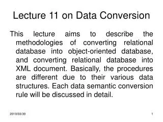
In this lecture, we explore the crucial stage of converting Entity-Relationship Diagrams (ERDs) into tables for database design. We examine how the relationships in ERDs influence table structures, specifically focusing on one-to-many (1:M) and many-to-many (M:M) relationships. Through examples, we discuss how to assign primary keys and foreign keys to effectively link tables and manage relationships. The importance of proper table setup, including unique identifiers and attribute allocation, is emphasized to ensure a robust database structure.

E N D
Database Design Concepts INFO1408 Lecture 10 Conversion to tables
Introduction • The entities in our ERDs become tables in our design • How do the relationships in our ERDs affect our table designs? • In this lecture we will look at posting identifiers to give foreign keys to link the tables together • Dealing with the relationships one at a time.
Post 1:M – many end Obligatory works on 1 M Employee Machine Every Machine has exactly oneEmployee, so we can post the primary key of Employee into the Machine table, thus forming a foreign key: Emp (emp#,…….) Machine (machine#, emp#,……..) • This is the most common pattern on any ERD • The dot by the “1” is irrelevant to the tables.
1:M – Many end optional table required works on 1 M Employee Machine We can’t use POSTING so we need a relationship table
Put the Primary Keys from each end in the new table Emp (emp#, …….) Machine: (machine#, ……..) Works_on (machine#,emp#,……..) • For a 1:M relationship table the many end always provides the Primary Key (Why? Remember the primary key determines each attribute) • Again, the dot by the “1” is irrelevant to the tables • We add a “table required” note to the diagram, but we do not add a new entity.
M:M Relationships All M:M relationships should have been decomposed during modelling. Refer to the lecture last week.
Post works on 1 1 Employee Machine 1:1 Optional:Obligatory • Every machine has exactly oneemployee, so we can post the employee number into the Machine table: • (optional end’s identifier into the mandatory end) Emp (emp#, …….) Machine (machine#, emp#,…...).
works on 1 1 Employee Machine 1:1 Optional:Optional table required • We can’t use POSTING • Therefore, the relationship must be represented by a new table
Emp (emp#, …….) Machine (machine#, …….., ) Works_on (emp#, machine#,……..) or Works_on (emp#, machine#,……..) Either can be the identifier.
works on 1 1 Employee Machine 1:1 Obligatory:Obligatory • Every employee works on exactly one machine, and every machine is worked on by exactly one employee • We could post both ways!
This should be collapsed into one table: Emp (emp#, emp_name,….., machine#, machine_location……..) • Basically avoid this pattern in ERDs - it usually means the two entities are really the same thing, and is rarely correct.
Summary of Mapping Rules • Here is an important summary of the Entity-Relationship Diagram to Table types mapping rules: The only dots (participation condition) shown are those which affect the structure of the tables Your final ER diagram should not show un-decomposed M:M relationships
Completing the tables • You should now have several tables from your E:R model • Each table will have a unique identifier or key field • Some tables will have a posted or foreign key • Finally allocate the attributes to a table- We will practice this in the tutorials
Some Examples • Represent the relationships on the following slides in the correct way, i.e. by either • collapsing into one table • posting the identifier of one table into the other • creating a table for the relationship.
Example 1 Game Player M 1 plays Player (player#, name, . . .) Game (game#, date, . . .)
Example 2 Store Manager 1 1 runs Manager (staff#, name, . . .) Store (store#, location,. . .)
Example 3 Sales Rep Vehicle 1 M allocated to • Vehicle (vehicle#, type, . . .) • Sales Rep (staff#, area, . . .)
Example 4 Projector Lecture Theatre 1 1 fitted with Lecture Theatre (room#, capacity, . . .) Projector (equipment#, date_purchased, . . .)
Summary • Conversion to tables is the last stage of the the E:R modelling process. • Learn the rules of what to do based on the properties of the relation ship. • The tables given will form the basis of the implementation. • The primary and foreign keys will have been identified • Take care to make sure all other attributes are only allocated to one table