Download

1 / 31
310 likes | 424 Views
o pensensor Part 5 Building the opensensor. o verview.

E N D
overview The main goal is to describe how to build or how to order the opensensor and as a discussion board dealing with the opensensor. Currently the opensensor board has version number 3.0. We offer here the full documentation for the hardware design of the opensensor. Also we offer to ship the opensensor or parts of it. Furthermore completed software projects on the opensensor are described and the software is available too.
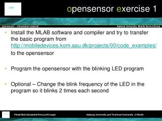
step 1 • Step 1 - backside • Take the PCB (printed circuit board, the green big thing) and look at the backside as in the picture.
step 2 • Step 2 - backside • Now solder U3 (MAX3232) on the PCB. We have two versions of this unit, a thin and a wide version. In the picture we have the thin one.
step 3 • Step 3 - front • Now you have to turn the PCB to the front. The backside is ready (you may come back to the backside to cut some of the legs of some of the units).
step 4 • Step 4 - front • Now you solder U5 (LM3940).
step 5 • Step 5 - front • Solder C11.
step 6 • Step 6 - front • Solder C12.
step 7 • Step 7 - front • Now solder U6. It is the voltage regulator.
step 8 • Step 8 - front • Now solder the capacities C5, C6, C7, C8, C8, C10, C13, C14, and C15 (do not be worry, all the same).
step 9 • Step 9 - front • Now solder D1 and D3. There are two different colors (red and green). Be aware, the longer leg of the LED is the plus pole.
step 10 • Step 10 - front • Now solder D2. Be aware of the direction!!!
step 11 • Step 11 - front • Now solder J1, J2, J5, and J6.
step 12 • Step 12 - front • Now solder X1 (22.184MHz).
step 13 • Step 13 - front • Now solder C2 and C4.
step 14 • Step 14 - front • Now solder U4 (nRF905 socket).
step 15 • Step 15 - front • Now solder the main socket for the DSPIC - U2.
step 16 • Step 16 - front • Now solder J7, the connector for the Pickit2.
step 17 • Step 17 - front • Now solder U1 if you have the Bluetooth chip (if not just skip this step).
step 18 • Step 18 - front • Now solder P1, a 9-pin D-sub 9 polfemale.
step 19 • Step 19 - front • Now solder R9 and R10.
step 20 • Step 20 - front • Now solder R7.
step 21 • Step 21 - front • Now solder R8.
step 22 • Step 22 - front • Now solder R5 and R6.
step 23 • Step 23 - front • Now solder R3.
step 24 • Step 24 - front • Now solder J3, J4, and J8.
step 25 • Step 25 - front • Now put the DSPIC into the socket (no soldering required) and (if any) plug in the nRF905.
step 26 • Step 26 - front • Connect the battery clip. The black cable to ground (1pin on J8) and the red one to VIN (6th pin on J8).
step 27 • Step 27 - backside • QUICKHACK: For opensensor 3.0 (newer PCBs will be corrected) we need to connect some pins as given in the picture. Any cable will be ok for that.
publication • F.H.P. Fitzek and F. Reichert. Mobile Phone Programming and its Application to Wireless Networking. 2007. Springer.