Download
1 / 15
520 likes | 1.54k Views
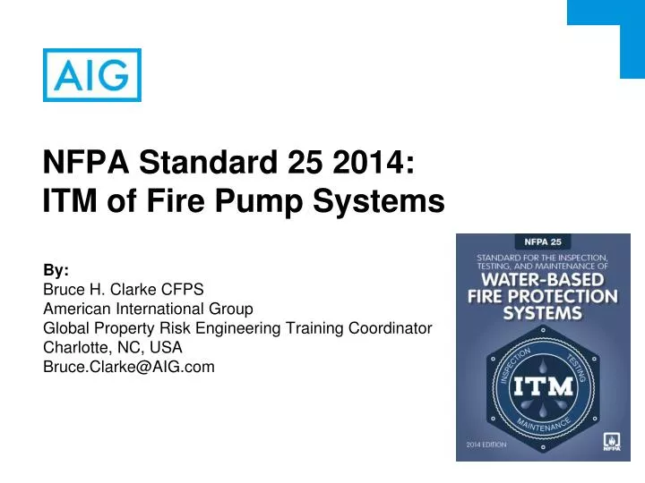
NFPA Standard 25 2014: ITM of Fire Pump Systems. By: Bruce H. Clarke CFPS American International Group Global Property Risk Engineering Training Coordinator Charlotte, NC, USA Bruce.Clarke@AIG.com. NFPA 25 Fire Pump ITM. Design & Installation Acceptance Testing.

E N D
NFPA Standard 25 2014:ITM of Fire Pump Systems By: Bruce H. Clarke CFPS American International Group Global Property Risk Engineering Training Coordinator Charlotte, NC, USA Bruce.Clarke@AIG.com
NFPA 25 Fire Pump ITM Design & Installation Acceptance Testing Inspection, Testing, and Maintenance after Acceptance Testing
NFPA 25 Fire Pump ITM Some other potential references/resources: • NFPA 13: Sprinkler systems • NFPA 14: Stand pipe systems • NFPA 22: Private service tanks • NFPA 24: Private service water mains • NFPA 70: Electrical systems • NFPA 72: Alarms • NFPA 110: Emergency/standby power systems • NFPA 1963: Hoses
NFPA 25 Fire Pump ITM Primary NFPA 25 references for ITM of fire pump systems: • Ch. 5: Sprinkler systems • Ch. 6: Hoses & standpipes • Ch. 7: Private water mains • Ch. 8: Pumps • Ch. 9: Tanks • Ch. 13: Valves • Ch. 14: Corrosion/obstructions • Ch. 15: Hoses • Ch. 16: Impairments
NFPA 25 Fire Pump ITM NFPA 25 inspection requirements include: • Valves open [8.2.2 (1)(a)] • Suction reservoir has required water level On [8.2.2(2)(e)] • Controller in auto [(8.2.2(4)(b)] • Controller battery back-up power is On [8.2.2(3)(c&d)] • Controller pilot light illuminated On [8.2.2(3)(a)] • Fuel tank at least 2/3 full [(8.2.2(4)(a)] • All alarm lights off [(8.2.2(4)(f)] • Battery electrolyte levels acceptable [(8.2.2(4)(k)]
NFPA 25 Fire Pump ITM NFPA 25 test requirements include: Churn testing: • Diesel-driven pumps- weekly churn(no flow) [8.3.1.1] • Or, based on approved risk analysis [8.3.1.1.2] • 30 minute minimum duration [8.3.2.4] • Electric-driven pumps- monthly churn(no flow) [8.3.1.2.1] • Or, weekly for high-rises, LS controllers, vertical turbines • Or, weekly for pumps with ground level tanks (or similar) • Or, back to monthly if there is redundancy • Or, based on approved risk analysis [8.3.1.2.4] • 10 minute minimum duration [8.3.2.3]
NFPA 25 Fire Pump ITM NFPA 25 test requirements include: Full flow testing: • No flow, 100%, 150% points [8.3.3.1] • Test with approved devices [8.3.3.1] • Flow meters acceptable every 2nd & 3rd year only [8.3.3.1.3] • Testing of alarm conditions [8.3.3.5] • “Routine” testing of associated emergency generators [8.3.6.1] • Degradation testing of diesel fuels [8.3.4]
NFPA 25 Fire Pump ITM NFPA 25 test requirements include: Full flow testing pump curve analysis requirements: • Step One [8.3.7.2.1]: • Check speed-adjusted net performance to pump curve/placard • Use 5% performance degradation as investigation trigger • Step Two [8.3.7.7]: • Check unadjusted gross performance to fire system demands • Use graphical results as investigation trigger
NFPA 25 Fire Pump ITM Step One: Pump Net Performance Evaluation Procedure[8.3.7.2.1]: • Adjust recorded gross flow and pressure performance data (discharge pressure-suction pressure) to the pump rated speed at each test point utilizing Affinity Law calculations. • Plot speed-adjusted performance curve overlaid on manufacturers original data sheet or pump placard-generated curve. • Determine if performance is within 5% of recorded “new” performance
NFPA 25 Fire Pump ITM Step Two: Pump Gross Performance Evaluation Procedure[8.3.7.7]: • Plot flow and pressure demand points of all fire protection systems supplied by fire pump on hydraulic graph paper. • Plot gross pump data performance curve (not adjusted for speed) overlaid. • Determine if gross discharge exceeds demands for fire protection systems being supplied.
NFPA 25 Fire Pump ITM PUMP TEST CRITICAL RULES for GOOD RESULTS: NO. 1: Physical test “acceptably” is based on methods and tools used. NO. 2: Pump performance “acceptability” is based on accuracy of the data collected and quality of analysis.