Download
1 / 25
281 likes | 489 Views
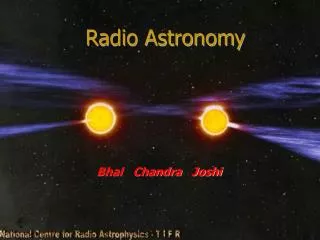
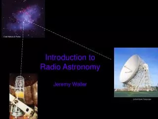
Introduction to Radio Astronomy Jeremy Waller. Crab Nebula & Pulsar. Jodrell Bank Telescope. 100” Hooker Telescope. Road Map. Ptolemy. Tycho Brahe. S & T. Keppler. Bayer. Galileo. Flamsteed. Newton. Refracting Telescope. S & T. Argelander. Siedel Abbe Schott Gauss. Maxwell.

E N D
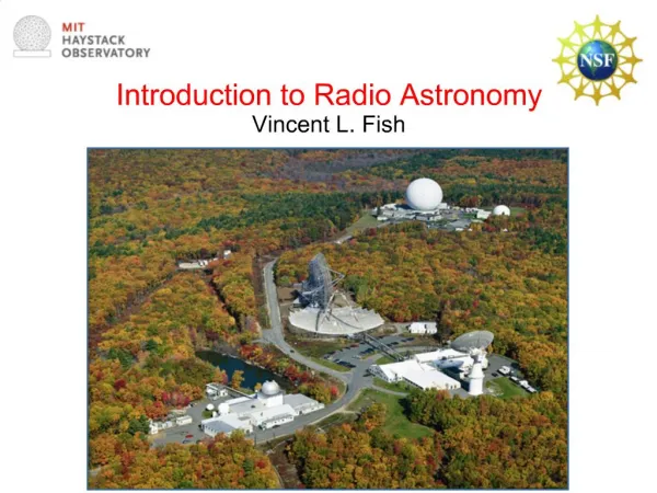
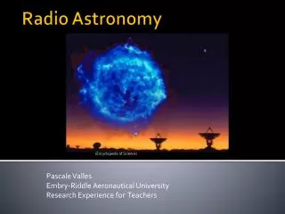
Introduction to Radio AstronomyJeremy Waller Crab Nebula & Pulsar Jodrell Bank Telescope 100” Hooker Telescope
Road Map Ptolemy Tycho Brahe S & T Keppler Bayer Galileo Flamsteed Newton Refracting Telescope S & T Argelander Siedel Abbe Schott Gauss Maxwell Hertz Communications WW2 Reflecting Telescope Jansky Antennas Aka: Radio Telescopes Reber Wiener Kolmogoroff Radio Visual Sky Map Satellite Comms. Astronomy Adaptive Optics Pulsars Quasars Radio Galaxies Planets Stars Sun DSP Interferometers VLA Statistical Communications
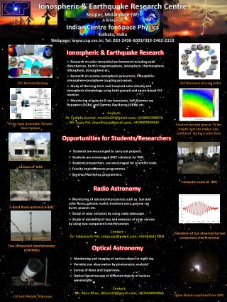
Brief History of Communications • Properties of Electromagnetic Radiation • -What is Electromagnetic Radiation? • -Frequency and Wavelength • -Inverse-Square Law of Propagation • Electromagnetic Spectrum • Causes of Electromagnetic Emissions • -Blackbody Characteristics • -Thermal Radiation • -Continuum Emissions • (eg. Planetry Nebulae, Galactic nuclei, Comets) • -Line Spectra Emission … Atoms and Molecules • -Other sources • Synchrotron Radiation • Representative Sources of RF • -Star • -Pulsar • -Jupiter • The Radio Telescope
Sources of RF: • Stars: • -Variable Stars • -Pulsars • -Sun • Galactic and Extragalactic Sources: • -Quasars • Planetary: • -Jupiter System • -Moon • -Comets • Sources of Interference: • -Sun • -Lightning • -Ionosphere • -Power grid, transformers, distribution • - Radars- military and others • -Radio and TV transmitters • -Satellite transmitters • -Mobile phones
History of Communications 1800 – 1837 Volta discovers the battery Mathematics – Laplace, Fourier, Cauchy Oersted, Ampere, Faraday, Henry, Ohms Law (1826) Early Telegraph Systems (Gauss & Weber) (Wheatstone & Cooke) 1838 – 1866 Birth of Telegraphy – Transatlantic cable (1866) Pulse Response of a cable calculated(1855) – Lord Kelvin. 1864 A Dynamical Theory of the Electromagnetic Field” J.C.Maxwell – Predicts EM Radiation 1876 – 1899 The Birth of Telephony Stowger devises the step by step switch. 1887-1907 Hertz verifies Maxwells theory 1904-1920 Electronics Applied to Radio and Telephone 1920-1928 Papers by Nyquist, Carson, Hartley
History of Communications – cont. 1923-1938 Birth of Television 1939-1945 – WW2 Radar and Microwave Systems developed Wiener and Kolmogoroff – Statistical Signal Detection 1948 A Mathematical Theory of Communication Claude Shannon. . . .
EM wave Propagates as a series Of Electric and Magnetic fields Time (t) E field E cw ccw H H field Time (t) “ Front View ” • Polarisation – Direction of E field Vector • Linear • -Vertical, Horizontal or other angle • Elliptical • - Circular • -RH or LH Field variation with time Notice: Electric field is closed - does not terminate on a charge.
Property of the Radiated Energy 3 m 9 2 m 4 1 m 1 Isotropic Radiator • Inverse Square Law • -Power per unit area • falls as the square of • the distance from the • source • Doubling the distance • reduces the power per • square metre by x4
Effects on RF Emissions • Earths Atmosphere • -Atmospheric “Windows” • -Absorption and Emission Lines • -Reflection • -Refraction • -Phase • -Scintillation • -Faraday Rotation • Source Motion & Gravity • -Doppler Effect • -Gravitational Red Shifting • -Gravitational Lensing • -Occultations
Atmospheric Absorption Spacecraft 100% Absorption Radio Telescopes 0% 4.54 mm … 66GHz.
Karl Jansky (engineer) • Bell Telephone Laboratories • - 1931` • - Identifying sources of interference • with radio telephone service. • - Rotatable Antenna tuned to 20.5 MHz • -Diameter … 100 ft (30 m). • -Height … 20 ft (6 m) • Three types of static: • -Nearby thunderstorms • -Distant thunderstorms, • -Faint hiss of unknown origin. • - Period 23 hours : 56 minutes. • Comparing the above observations with optical astronomical maps • Conclusion: • -The radiation (Hiss) was coming from the Milky Way • -Peaked in the direction of the centre of the galaxy, • in the constellation of Sagittarius.
Grote Reber • -Pioneer of Radio Astronomy • -9 m Paraboloidal antenna (1937) … Radio Telescope • -Repeats Jansky’s work • -Conducts the first sky survey in the radio frequencies.
Pulsars as an example Jocelyn Bell Discovers the Pulsar in 1967 • RadioTelescope: • -2000 dipoles • -4.5 acres and • -Operational in July 1967 • -Aperture Synthesis
Strong Radio Sources: (Radiance … Jansky) 10 MHz 100 MHz 1 GHz 10 GHz Cassiopeia A 100000 19500 3300 1000 Supernova remnant Cygnus A 70000 13800 2340 300 Radio galaxy Sagittarius A 4000 2000 Center of our galaxy Centaurus A 3000 2000 Peculiar galaxy Virgo A 10000 1800 250 100 M87, galaxy with "jet" Taurus A 1700 955 M1 - Crab Nebula - SN remnant Sun, quiet100 10 000 100 000 1E+6 Sun, disturbed 1E+7 1E+8 1E+8 1E+8 Moon0.1 3 50 10000 Jupiter 1E+7 0 0 50 Sky background 2E+7 3E+6 1E+6 3E+5 Source: "Radio Astronomy" by Kraus, McGraw-Hill 1966
Milky Way in Various Wavelengths: Infra-Red Radio X-Ray Visible From Griffith Observatory and JPL),
Radio continuum emission Example • (Staff Research at AAT) • Gamma Velorum • - Nearest and brightest Wolf Rayet star • -Binary system with an O-star • companion and an orbital period of 79 days. • -Radio Continuum RF @ 10 GHz (3 cm) • -30 mJansky • Observation • RF is non-thermal in origin and • arises from shock fronts which form as the stellar wind from the Wolf Rayet star collides with the stellar wind of the O-star. • Monitoring continuum RF at 3, 6, 13 and 20 cm over a three-month period. Initial results indicate that radio variability is indeed present.
Pulsar as an example • Tutorial on Pulsars – Jodrell Bank • http://www.jb.man.ac.uk/~pulsar/Education/Tutorial/tut/tut.htm • -Duty cycle ~ 5% -Some Individual pulses very variable in intensity -Stable profile if several hundred pulses added -Strongly linearly polarised -Monotonic polarisation position angle swing through • the pulse implies the origin is near a magnetic pole • -Very high brightness temperature implies coherent emission -Drifting subpulses -Mode changing
The lighthouse model of a radio pulsar: A rapidly central neutron star with a strong magnetic field, inclined to the rotation axis with radio emission emanating from the magnetic poles The lighthouse model of a radio pulsar: Wobble in the spin axis
Radio Emissions From Jupiter Bernard Burke and Kenneth Franklin of the Carnegie Institution in Washington D.C. discovered that the planet Jupiter was a strong source of radio waves. One arm of Mills Cross Array (circa 1954)
Radio Emissions From Jupiter • Synchrotron radiation between 70MHz to over 20 GHz • - At < 40 MHz the planet’s radio emission • is dominated by emissions many orders stronger • than the synchrotron radiation. • 1E+7 J @ 10 MHz. • Known causes • Planetary rotation modulation, • Modulation by Io and/or its torus, • Influence by the solar wind. • Significant number of radio variations • are not currently explained by any known mechanism.
Prime Focus Feed Casagrain Feed Secondary Reflector • The Radio Telescope: • -Antenna • -Single Antenna • -Array Antenna • -Receiver • -Low Noise front end • -Signal Processing • -Depends on what • one wants done !! Paraboloidal Reflector Antenna Array
The Radio Telescope • Will be quite Large • Need extremely high Resolution at the longer wavelengths • Looking for very weak signals • -Very distant sources • Emissions may be weak (eg. Gamma Velorum) • -eg Continuum emissions Receiver Channel #1 ADC IF Amp Frequency Translation Low Noise Amp Antenna Control R 21 Antenna & Receiver Array R 11 R 22 • Signal Processing System • -Experiment (?) • -Beam Forming • -Aperture synthesis • -Signal Enhancement and Detection • -Signal Properties • -Signal Strength (t) • -RF Doppler • -Polarisation • -Image forming R 01 R 12 R 23 R 02 R 13 R 03
THE END • Any Questions ? • SETI • Discussions at the Maid and Magpie • Date? … TBD