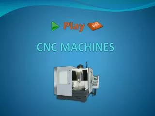
CNC
CNC. GOVT POLYTECHNIC AMBALA CITY. CHAPTER 1. INTRODUCTION. Introduction to NC. Production of machined parts whose production is controlled by a computer . Definition:

CNC
E N D
Presentation Transcript
CNC GOVT POLYTECHNIC AMBALA CITY
CHAPTER 1 • INTRODUCTION
Introduction to NC • Production of machined parts whose production is controlled by a computer. Definition: • NC - A method of accurately controlling the operation of a machine tool by a series of coded instructions, consisting of numbers, letters of the alphabet, and symbols that the machine control unit can understand The concept of NC was proposed in 1940s by JohnParsons who recommended a method of automatic machine control that would guide a milling cutter to produce a curvilinear motion in order to generate smooth profiles on the work-pieces.
Evolution of NC/CNC • Single items produced by craftspeople • Interchangeable Parts • Eli Whitney (Cotton Gin) • Manual labor was still the most cost effective method. • WW II manufacturers could not maintain quantity & quality parts.
Three basic components of an NC system: • Input medium: - Part program or instructions needed to drive the machine tool components - Instructions are prepared manually or by use of computer - Instructions include machining parameters (feed rate, cutting speed); sequence of actions (e.g., positioning & machine functions) - Instructions are stored in the form of tape (paper, magnetic); floppy diskettes; DNC download to CNC RAM 2. Machine control unit (MCU): - Electronics & control hardware - Interpret instruction set - Execute instructions - Monitor results & correct where appropriate 3. Machine tool: - Mechanical structure that performs the machining, including the components that drive each axis of motion (e.g., AC or DC motor; hydraulic actuator; stepper motor — choice affects speed of response, accuracy and power capacity).
INPUT UNIT • Input data includes information about the control medium, information about computer programs should also be given. • Control medium: perforated tape, magnatic tape, etc. • Type of dimensional programming: Absolute, Incremental or both etc., • Number of digits in each dimensional word etc., Input resolution Information about programming methods and languages • Tape reader type - Mechanical or photo electric etc., Tape code - ISO, EIA
MCU • MCU - Machine Control Unit - decodes NC codes to drive and monitor servo motor movements.
CNC Advantages vs. NC • Programs could be stored in computer memory. • Easier to edit. • More complex parts could be manufactured. • Use of 3d geometry. • Networking/filesharing w/ other computers.
Limitations of NC • Relatively high initial cost of equipment. • · Need for part programming. • · Special maintenance requirements. • · More costly breakdowns.
Advantages Of CNC • Increased productivity after programming is completed • Reliability - reduces human error • Often eliminates need for special jigs and fixtures • Reduces location of part features • Makes possible the machining of complex shapes requiring simultaneous 3 axis motion • Single part and production runs can be programmed and machined with minimum effort and cost. • Programs can readily be altered and re-run • Reduced inspection costs (more reliable) • Once programming, setup and verified the equipment can be operated by a less skilled operator.
Disadvantagesof CNC • Initial cost of CNC machine tools • Servicing of equipment • Larger machines require more space • Personnel must be trained in the programming and operation of this equipment.
Direct Numerical Control (DNC) • Distributed (Direct) Numerical Control (DNC): · • (Direct) Central computer stores programs & directs NC operations; NC machines dependent on central computer. • (Distributed) Central computer stores programs and transfers programs to CNC machines. • Central computer provides management functions (e.g., part of MIS) Programs stored as cutter location (CL) files and post-processed for the machine assigned the job. • Major components: central computer; bulk memory; telecommunication (EDI); CNC machine tools.
Selection of components for NC/CNC 1. Parts from similar raw material, in variety of sizes, and/or complex geometries. 2. Low-to-medium part quantity production. 3. Similar processing operations & sequences among work pieces. 4. Frequent changeover of machine for different part numbers. 5. Meet tight tolerance requirements (compared to similar conventional machine tools).
Application of CNC Machine Tools • CNC mills and machining centers, • CNC lathes and turning centers • CNC electrical discharge machining (EDM) • CNC grinding machines • CNC cutting machines (laser, plasma, electron, or flame) • CNC fabrication machines (sheet metal punch press, bending machine, or press brake) • CNC welding machines
AXIS IDENTIFICATION 2&3 axes CNC Machines CNC lathes will be coming under 2 axes machines. There will be two axes along which motion takes place. The saddle will be moving longitudinally on the bed (Z-axis) and the cross slide moves transversely on the saddle (along X-axis). In 3-axes machines, there will be one more axis, perpendicular to the above two axes.
CHAPTER 2 • CONSTRUCTION AND TOOLING
MAIN ELEMENTS OF CNC MACHINES • To enable electronic automation with high rate of metal removal at optimum cutting conditions, maintaining high repetitive accuracies with utmost safety to the operator and the machine, CNC machines are specially designed.
MAIN ELEMENTS OF CNC MACHINES • i) Machine structure • ii) Guide ways • iii) Spindle bearings & mounting • iv) Drive units • v) Mech. Power transmission • vi) Position feed back elements / systems • vii) Additional accessories / equipment • viii) Control software • ix) Chip removal system • x) Safety features
Machine structure • Structures are designed to withstand static, dynamic & thermal loads providing high stiffness, rigidity & damping properties. The material used is generally mechanite • cast iron / special casting with nickel & copper elements. Welded structures also in wide usage.
Guide ways • TYPES OF GUIDE WAYS • 1. Friction Guide ways: The relation between moving part (Guide) and stationary part (Guide way) contacting directly each other. • 2. Anti Friction Linear Motion Guide ways: Here the contact between guide and guide way may be separated by the third element i.e. Ball, Roller or hydraulic oil film in case of Hydro dynamic or hydrostatic guide way systems.
1) HYDROSTATIC GUIDE WAY • 2) AEROSTATIC GUIDE WAY In Hydrostatic guide ways, the surface of slide is separated from the guide way by a very thin film of fluid supplied at pressure as high as 300 bar. Frictional wear and stick slip are entirely eliminated. A high degree of dynamic stiffness and damping are obtained with these guide ways, both characteristics contributing to good machining capabilities. Their application is limited due to high cost and difficulty in assembly. In Aerostatic guide ways, the slide is raised on a cushion of compressed air which entirely separates the slide and the guide way surfaces. The major limitation of this type guide ways is a low stiffness, which limits its use for positioning application only. e.g. CMM and other measuring instruments.
RE CIRCULATING BALL BUSHINGS The following are the advantages of the ball screws: • 1) Low frictional resistance. • 2) Low drive power requirement. • 3) Lesser temperature rise. • 4) Less wear hence longer life. • 5) No stick slip effect. • 6) High traverse speed. • 7) High efficiency
There are two types of roller screws used planetary and re circulating. Both types provide backlash-free movement and their efficiency is of the same order (90 %) as ball screws. An advantage of roller screws is that because the pitch of the screw is smaller that the minimum pitch of the ball screw, the less complex electronic circuitry will provide more accurate positional control. Roller screws are much costlier than the ball screws. The rollers of both types of screw are positioned between the nut and the screw, and engage with the thread from inside the nut and on the outside of the screw.
GuidewaysThe guideways of CNC machines are made of steel. To reduce the frictional forces, they are coated with a strip of PTFE (Poly Tetra Fluoro Ethylene).
BallscrewsOn conventional lathes a leadscrew is used to converts the rotary motion of the hand wheel into linear motion of the slides. Leadscrews have a high coefficient of friction and backlash. On CNC machines a ballscrew is used instead of a leadscrew. Friction and backlash are much less than on leadscrews.
Swarf Removal • Efficient chip removal system eliminates thermal effects & thus improves the quality of cutting and the job being machined. • Centrifuging of chips at source integrated into a swarf blowing system • Airflow isolation slide damper • Rotary valve • Blowline inlet connection
Safety • Suitable covers for guide-ways etc., and electronic interlocks for the safety of the operating personnel and machine are provided.
AUTOMATIC TOOL CHANGER • HYDROMOTOR IS USED FOR THE ROTATION OF THE MAGAZINE. • MAGAZINE MOVES IN RAPID ONE TOOL AHEAD (SENSED BY PROXIMITY SWITCH) • MAGAZINE CREEPS TO THE POSITION IN A VERY LOW SPEED (SENSED BY PROXIMITY SWITCH). • WHEN THE MAGAZINE IS IN POSITION, LOCATING PIN ENTERS THE HOLE IN THE MAGAZINE AND POSITIONS THE MAGAZINE ACCURATELY.
ATC • Simple CNC machines work with a single tool. Turrets can work with a large number of tools. But if even more tools are required, then ATC is provided. The tools are stored on a magazine. It allows the machine to work with a large number of tools without an operator. The main parts of an automatic tool changer are the base, the gripper arm, the tool holder, the support arm and tool magazines.
Types of ATC • Depending on the shape of the magazine, ATC can be of two types: Drum Type changers are used when the number of tools is lower than 30. The tools are stored on the periphery of the drum. Chain type changers are used when the number of tools is higher than 30(The number is different depending on the design and manufacturer. It is important to note that the number of tools for the drum type is fewer than the chain type). But the tool search speed will be lower in this case
Programming Methods-APT • Part definition • P1=Point/12,20,0 • C1=Circle/Center,P1,Radius,3 • LN1=Line/C1. ATANGL,90 • Cutter Commands • TLRT,GORT/LN1.TANTO,C1 • GOFWD/C1,TANTO,L5
Programming Methods-CAM • Computer Aided Machining (CAM) Systems • Graphic representation of the part • PC based • Integrated CAD/CAM functionality • “Some” built-in expertise • Speed & feed data based on material and tool specifications
Programming Methods-CAM • Tool & material libraries • Tool path simulation • Tool path editing • Tool path optimization • Cut time calculations for cost estimating
Programming Methods-CAM • Import / export capabilities to other systems • Examples: • Drawing Exchange Format (DXF) • Initial Graphics Exchange Standard (IGES)
The Process CAD to NC File • Start with graphic representation of part • Direct input • Import from external system • Example DXF / IGES • 2D or 3D scan • Model or Blueprint (At this point you have a graphics file of your geometry)
The Process CAD to NC File • Define cutter path by selecting geometry • Contours • Pockets • Hole patterns • Surfaces • Volume to be removed (At this point the system knows what you want to cut)
The Process CAD to NC File • Define cut parameters • Tool information • Type, Rpm, Feed • Cut method • Example - Pocket mill zig-zag, spiral, inside-out • Rough and finish parameters (At this point the system knows how you want to cut the part)