Download
1 / 39
390 likes | 417 Views
Solve for i3(t) after switch from A to C in a circuit. Steps on RL Natural Response, Step Response, and Inductive Definitions.

E N D
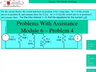
For the circuit shown, the switch had been in position A for a long time. At t = 0 the switch moves to position B, and remains there for 0.1[s].At t = 0.1[s] the switch moves to position C, and remains there. For the time interval t > 0, find the equations for the current i3(t). Problems With AssistanceModule 6 – Problem 4 Filename: PWA_Mod06_Prob04.ppt Go straight to the First Step Go straight to the Problem Statement Next slide
Overview of this Problem In this problem, we will use the following concepts: • RL Natural Response • RL Step Response • Defining Equation for Inductors Go straight to the First Step Go straight to the Problem Statement Next slide
Textbook Coverage The material for this problem is covered in your textbook in the following sections: • Circuits by Carlson: Sections #.# • Electric Circuits 6th Ed. by Nilsson and Riedel: Sections #.# • Basic Engineering Circuit Analysis 6th Ed. by Irwin and Wu: Section #.# • Fundamentals of Electric Circuits by Alexander and Sadiku: Sections #.# • Introduction to Electric Circuits 2nd Ed. by Dorf: Sections #-# Next slide
Coverage in this Module The material for this problem is covered in this module in the following presentations: • DPKC_Mod06_Part01 • DPKC_Mod06_Part02 • DPKC_Mod06_Part03 • DPKC_Mod06_Part04 Next slide
Problem Statement For the circuit shown, the switch had been in position A for a long time. At t = 0 the switch moves to position B, and remains there for 0.1[s].At t = 0.1[s] the switch moves to position C, and remains there. For the time interval t > 0, find the equations for the current i3(t). Next slide
Solution – First Step – Where to Start? For the circuit shown, the switch had been in position A for a long time. At t = 0 the switch moves to position B, and remains there for 0.1[s].At t = 0.1[s] the switch moves to position C, and remains there. For the time interval t > 0, find the equations for the current i3(t). How should we start this problem? What is the first step? Next slide
Problem Solution – First Step For the circuit shown, the switch had been in position A for a long time. At t = 0 the switch moves to position B, and remains there for 0.1[s].At t = 0.1[s] the switch moves to position C, and remains there. For the time interval t > 0, find the equations for the current i3(t). • How should we start this problem? What is the first step? • Redraw the circuit for t < 0. • Find the Norton equivalent seen by the inductor. • Define the inductive current. • Redraw the circuit for t > 0.
Your Choice for First Step –Redraw the circuit for t < 0 For the circuit shown, the switch had been in position A for a long time. At t = 0 the switch moves to position B, and remains there for 0.1[s].At t = 0.1[s] the switch moves to position C, and remains there. For the time interval t > 0, find the equations for the current i3(t). This is not the best choice. It is true that we will be doing this very shortly. However, it should not be done yet. The problem here is that the current i3 may change instantaneously when a switch is thrown. Thus, solving for it directly can cause problems. Ask yourself, what should I solve for first, and then go back and try again.
Your Choice for First Step –Find the Norton equivalent seen by the inductor For the circuit shown, the switch had been in position A for a long time. At t = 0 the switch moves to position B, and remains there for 0.1[s].At t = 0.1[s] the switch moves to position C, and remains there. For the time interval t > 0, find the equations for the current i3(t). This is not the best choice. The problem here is that it is not clear what position the switches will be in when you do this. For different time periods, you will have different answers. It is too soon to do this. Please, go back and try again.
Your Choice for First Step –Define the inductive current For the circuit shown, the switch had been in position A for a long time. At t = 0 the switch moves to position B, and remains there for 0.1[s].At t = 0.1[s] the switch moves to position C, and remains there. For the time interval t > 0, find the equations for the current i3(t). This is the best choice for the first step. The problem here is that the current i3 may change instantaneously when a switch is thrown. Thus, solving for it directly can cause problems. However, by solving for the inductive current first, we can then use this inductive current to solve for any other desired quantities. Let’s define the inductive current.
Your Choice for First Step –Redraw the circuit for t > 0 For the circuit shown, the switch had been in position A for a long time. At t = 0 the switch moves to position B, and remains there for 0.1[s].At t = 0.1[s] the switch moves to position C, and remains there. For the time interval t > 0, find the equations for the current i3(t). This is not the best choice. It is true that we will be doing this eventually. However, there is another switching event that will take place at t = 0.1[s]. Thus, the circuit will change then. In any case, it is premature to begin doing these things. Ask yourself, what should I solve for first, and then go back and try again.
Defining the Inductive Current For the circuit shown, the switch had been in position A for a long time. At t = 0 the switch moves to position B, and remains there for 0.1[s].At t = 0.1[s] the switch moves to position C, and remains there. For the time interval t > 0, find the equations for the current i3(t). The polarity that we choose for this does not matter. However, choosing a polarity does matter. • We have defined the inductive current. What should the second step be? • Redraw the circuit for t < 0, with the inductor as a short circuit. • Redraw the circuit for t < 0, with the inductor as an open circuit. • Redraw the circuit for t > 0 , with the inductor as a short circuit. • Redraw the circuit for t > 0 , with the inductor as an open circuit.
Your Choice for Second Step –Redraw the circuit for t < 0, inductor as a short circuit For the circuit shown, the switch had been in position A for a long time. At t = 0 the switch moves to position B, and remains there for 0.1[s].At t = 0.1[s] the switch moves to position C, and remains there. For the time interval t > 0, find the equations for the current i3(t). This is the best choice for the second step. We have been told that the circuit had been in this condition for a long time. With this kind of circuit (constant voltage source, Thevenin equivalent seen by the inductor) this will mean that the inductor will behave as a short circuit. Let’s redraw this circuit for t < 0.
Your Choice for Second Step –Redraw the circuit for t < 0, inductor as open circuit For the circuit shown, the switch had been in position A for a long time. At t = 0 the switch moves to position B, and remains there for 0.1[s].At t = 0.1[s] the switch moves to position C, and remains there. For the time interval t > 0, find the equations for the current i3(t). This is not a good choice for the second step. The inductor will not act as an open circuit here. The key is what behavior for the inductor results from the conditions here. Consider this question carefully. Please go back and try again.
Your Choice for Second Step –Redraw the circuit for t > 0, inductor as a short circuit For the circuit shown, the switch had been in position A for a long time. At t = 0 the switch moves to position B, and remains there for 0.1[s].At t = 0.1[s] the switch moves to position C, and remains there. For the time interval t > 0, find the equations for the current i3(t). This is not a good choice for the second step. It is not even clear what this would mean, since the time period t > 0 results in more than one condition, one before t = 0.1[s], and one after that. In any case, we generally need to start at earlier times to set up initial conditions. Please go back and try again.
Your Choice for Second Step –Redraw the circuit for t > 0, inductor as open circuit For the circuit shown, the switch had been in position A for a long time. At t = 0 the switch moves to position B, and remains there for 0.1[s].At t = 0.1[s] the switch moves to position C, and remains there. For the time interval t > 0, find the equations for the current i3(t). This is not a good choice for the second step. It is not even clear what this would mean, since the time period t > 0 results in more than one condition, one before t = 0.1[s], and one after that. In any case, we generally need to start at earlier times to set up initial conditions. In addition, we should note that the steady state condition for an inductor is a short circuit, since the voltage is zero for no change in current. Please go back and try again.
Redrawing the Circuit for t < 0 For the circuit shown, the switch had been in position A for a long time. At t = 0 the switch moves to position B, and remains there for 0.1[s].At t = 0.1[s] the switch moves to position C, and remains there. For the time interval t > 0, find the equations for the current i3(t). The inductor has been redrawn as a short circuit, since the circuit was in this condition for a long time, and had the opportunity to reach a steady-state condition. Let’s solve for iL(0).
Solving for vC(0) For the circuit shown, the switch had been in position A for a long time. At t = 0 the switch moves to position B, and remains there for 0.1[s].At t = 0.1[s] the switch moves to position C, and remains there. For the time interval t > 0, find the equations for the current i3(t). To solve for iL(0), we recognize that the voltage across the 10[W] resistor is 100[V], and write Next Slide
What is the Third Step? For the circuit shown, the switch had been in position A for a long time. At t = 0 the switch moves to position B, and remains there for 0.1[s].At t = 0.1[s] the switch moves to position C, and remains there. For the time interval t > 0, find the equations for the current i3(t). • We have found the initial condition we wanted. What should be the third step? • Redraw for t > 0. • Redraw for 0 < t < 0.1[s]. • Redraw for t > 0.1[s].
Your Choice for Third Step –Redraw for t > 0 For the circuit shown, the switch had been in position A for a long time. At t = 0 the switch moves to position B, and remains there for 0.1[s].At t = 0.1[s] the switch moves to position C, and remains there. For the time interval t > 0, find the equations for the current i3(t). This is not a good choice for the third step. It is not even clear what this would mean, since the switch moves again at t = 0.1[s]. The key here is to draw the circuit for a given time period, where the switches are all in known positions, and then solve. The time period given here does not meet this criterion, since the switch moves in this time period. Please go back and try again.
Your Choice for Third Step –Redraw for 0 < t < 0.1[s] For the circuit shown, the switch had been in position A for a long time. At t = 0 the switch moves to position B, and remains there for 0.1[s].At t = 0.1[s] the switch moves to position C, and remains there. For the time interval t > 0, find the equations for the current i3(t). This is the best choice for the third step. This is the time period for the next time of interest. During this time period, no switches close or open. Let’s redraw for this time period.
Your Choice for Third Step –Redraw for t > 0.1[s] For the circuit shown, the switch had been in position A for a long time. At t = 0 the switch moves to position B, and remains there for 0.1[s].At t = 0.1[s] the switch moves to position C, and remains there. For the time interval t > 0, find the equations for the current i3(t). This is a good choice for the third step, but it is not the choice that we will choose. During this time period, no switches close or open. However, it just seems reasonable to work through the problem chronologically, and so the time period 0 < t <0.1[s] makes sense as the next period to consider. In addition, the initial condition for the last time period will be obtained from the time period 0 < t < 0.1[s]. Let’s redraw for this time period.
Redrawing the Circuit for 0 < t < 0.1[s] For the circuit shown, the switch had been in position A for a long time. At t = 0 the switch moves to position B, and remains there for 0.1[s].At t = 0.1[s] the switch moves to position C, and remains there. For the time interval t > 0, find the equations for the current i3(t). We have redrawn the circuit for 0 < t < 0.1[s] in the circuit at right, above. This circuit is a natural response circuit. The initial condition is known, so the only unknown quantity in the solution is the time constant. The equivalent resistance seen by the inductor is easily seen to be R3 in this circuit, so The inductor has been redrawn as an inductor, since the circuit has not had a chance to reach a steady-state condition. Next Slide
Solution for 0 < t < 0.1[s] For the circuit shown, the switch had been in position A for a long time. At t = 0 the switch moves to position B, and remains there for 0.1[s].At t = 0.1[s] the switch moves to position C, and remains there. For the time interval t > 0, find the equations for the current i3(t). The natural response solution, then is This gives us the first part of our solution, which is Next Slide
Solution for 0 < t < 0.1[s], Note 1 For the circuit shown, the switch had been in position A for a long time. At t = 0 the switch moves to position B, and remains there for 0.1[s].At t = 0.1[s] the switch moves to position C, and remains there. For the time interval t > 0, find the equations for the current i3(t). Note that we use the symbol £ in this solution, since it is for an inductive current. An inductive current up to the time of switching, must be valid at the time of switching, too, since it cannot change instantaneously. Next Slide
Solution for 0 < t < 0.1[s], Note 2 For the circuit shown, the switch had been in position A for a long time. At t = 0 the switch moves to position B, and remains there for 0.1[s].At t = 0.1[s] the switch moves to position C, and remains there. For the time interval t > 0, find the equations for the current i3(t). Note that we use the symbol < in this solution, since it is not for an inductive current. This current, i3(t), can change instantaneously. Thus, this solution is only valid at times when the switching does not take place. In particular, we would note that i3(0-) = 0, but i3(0+) = -10[A]. Next Slide
What is the Fourth Step? For the circuit shown, the switch had been in position A for a long time. At t = 0 the switch moves to position B, and remains there for 0.1[s].At t = 0.1[s] the switch moves to position C, and remains there. For the time interval t > 0, find the equations for the current i3(t). • We have found the first part of the solution that we wanted. What should be the fourth step? • Find iL(0.1[s]). • Find i3(0.1[s]).
Your Choice for Fourth Step –Find iL(0.1[s]) For the circuit shown, the switch had been in position A for a long time. At t = 0 the switch moves to position B, and remains there for 0.1[s].At t = 0.1[s] the switch moves to position C, and remains there. For the time interval t > 0, find the equations for the current i3(t). This is the best choice for the fourth step. We need to have an initial condition for the next time period. The inductive current cannot change instantaneously, so it is a good thing to find for an initial condition. Let’s find iL(0.1[s]).
Your Choice for Fourth Step –Find i3(0.1[s]) For the circuit shown, the switch had been in position A for a long time. At t = 0 the switch moves to position B, and remains there for 0.1[s].At t = 0.1[s] the switch moves to position C, and remains there. For the time interval t > 0, find the equations for the current i3(t). This is not a good choice for the fourth step. We need to have an initial condition for the next time period. However, the current i3 can change instantaneously, and so it is difficult to find. Instead, let’s find iL(0.1[s]).
Finding iL(0.1[s]) For the circuit shown, the switch had been in position A for a long time. At t = 0 the switch moves to position B, and remains there for 0.1[s].At t = 0.1[s] the switch moves to position C, and remains there. For the time interval t > 0, find the equations for the current i3(t). Next Slide The inductive current cannot change instantaneously, so it is a good thing to find for an initial condition. Therefore, we plug in to find iL(0.1[s]),
Redrawing the Circuit for t > 0.1[s] For the circuit shown, the switch had been in position A for a long time. At t = 0 the switch moves to position B, and remains there for 0.1[s].At t = 0.1[s] the switch moves to position C, and remains there. For the time interval t > 0, find the equations for the current i3(t). • Here we have the circuit for the third time period. We need is the Thevenin resistance, which will give us the time constant. Which value do you think is the resistance seen by the inductor? • 60[W] || 60[W] = 30[W] • 60[W] || 20[W] = 15[W]
Your Choice for REQ –30[W] For the circuit shown, the switch had been in position A for a long time. At t = 0 the switch moves to position B, and remains there for 0.1[s].At t = 0.1[s] the switch moves to position C, and remains there. For the time interval t > 0, find the equations for the current i3(t). This is the correct answer. When we set the current source equal to zero, we have R3 || (R4 + R5), which is 30[W]. Thus, the time constant, t = L/REQ = 0.2[s]. Now, let’s find the final value for iL(t).
Your Choice for REQ –15[W] For the circuit shown, the switch had been in position A for a long time. At t = 0 the switch moves to position B, and remains there for 0.1[s].At t = 0.1[s] the switch moves to position C, and remains there. For the time interval t > 0, find the equations for the current i3(t). This is the wrong answer. When we set the current source equal to zero, we have R3 || (R4 + R5), which is 30[W]. The current source does not short out R5 here when it is set equal to zero. Thus, the time constant, t = L/REQ = 0.2[s]. Now, let’s find the final value for iL(t).
Finding the Final Value for iL(t) For the circuit shown, the switch had been in position A for a long time. At t = 0 the switch moves to position B, and remains there for 0.1[s].At t = 0.1[s] the switch moves to position C, and remains there. For the time interval t > 0, find the equations for the current i3(t). We want to redraw for t = ¥, so we have the circuit below. Note that the inductor becomes a short circuit, since it reaches a constant steady-state value. Next, we will use CDR to find iL(¥).
Using CDR to get Final Value for iL(t) For the circuit shown, the switch had been in position A for a long time. At t = 0 the switch moves to position B, and remains there for 0.1[s].At t = 0.1[s] the switch moves to position C, and remains there. For the time interval t > 0, find the equations for the current i3(t). We want to redraw for t = ¥, so we have the circuit below. Note that the inductor becomes a short circuit, since it reaches a constant steady-state value. Writing KVL around the loop, we get Next, we will use these quantities to find iL(t).
Finding iL(t) for t > 0.1[s] For the circuit shown, the switch had been in position A for a long time. At t = 0 the switch moves to position B, and remains there for 0.1[s].At t = 0.1[s] the switch moves to position C, and remains there. For the time interval t > 0, find the equations for the current i3(t). We can substitute what we know into the equation for iL(t), Finally, we have everything we need to find i3(t).
Finding i3(t) for t > 0.1[s] For the circuit shown, the switch had been in position A for a long time. At t = 0 the switch moves to position B, and remains there for 0.1[s].At t = 0.1[s] the switch moves to position C, and remains there. For the time interval t > 0, find the equations for the current i3(t). We choose to define the voltage across the inductor, vL, at this point. We can find this voltage, using the defining equation for the inductor. We get our solution on the next slide. Note that we use the symbol “>”in this solution, since it is not for an inductive current.
The Solution for i3(t) for t > 0.1[s] For the circuit shown, the switch had been in position A for a long time. At t = 0 the switch moves to position B, and remains there for 0.1[s].At t = 0.1[s] the switch moves to position C, and remains there. For the time interval t > 0, find the equations for the current i3(t). Using Ohm’s Law for the R3 resistor, we have Note that the current i3(t) makes a step jump at t = 0, and at t = 0.1[s], the two switching times. The other part of the solution that we found earlier was Go to the Comments Slide
This seems to take a long time, doesn’t it? • Yes, this kind of problem takes longer than many of the problems we have worked up to this point. And, it may seem that we are taking a very roundabout approach to the solution by solving for the inductive current or capacitive voltage first, even if we are not asked to find them. • However, for most beginning students, using this approach makes getting the correct answer more likely, which is a very good thing. One way of looking at this is that many engineering problems are this way; by taking a consistent, reliable approach, we may save time in the long run by avoiding errors. Go back to Overviewslide.