Download
1 / 40
590 likes | 1.27k Views
Unit-2 Polarization and Dispersion. Wavelength . E o. z. Phase. Phase velocity. One Dimensional EM Wave. For most purposes, a travelling light wave can be presented as a one-dimensional, scalar wave provided it has a direction of propagation.

E N D
Wavelength Eo z Phase Phase velocity One Dimensional EM Wave • For most purposes, a travelling light wave can be presented as a • one-dimensional, scalar wave provided it has a direction of • propagation. • Such a wave is usually described in terms of the electric field E. A plane wave propagating in the direction of z is: The propagation constant (or wave number) n = Propagation medium refractive index
1.49 ng 1.46 Ref. index Phase velocity n 1.44 1900 500 1700 (nm) Group Velocity • As monochromatic light wave propagates along a waveguide in the • z direction, the points of constant phase travel at a phase velocity. • However, non-monochromatic waves travelling • together will have a velocity known as Group Velocity: Where the fibre group index is:
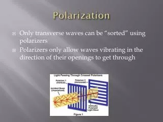
Classification of Polarization • Light in the form of a plane wave in space is said to be linearly polarized. • If light is composed of two plane waves of equal amplitude by differing in phase by 90°, then the light is said to be circularly polarized. • If two plane waves of differing amplitude are related in phase by 90°, or if the relative phase is other than 90° then the light is said to be elliptically polarized.
Linear Polarization • A plane electromagnetic wave is said to be linearly polarized. • The transverse electric field wave is accompanied by a magnetic field wave as illustrated.
Circular Polarization • Circularly polarized light consists of two perpendicular electromagnetic plane waves of equal amplitude and 90° difference in phase. • The light illustrated is right- circularly polarized.
Elliptical Polarization • Elliptically polarized light consists of two perpendicular waves of unequal amplitude which differ in phase by 90°. • The illustration shows right- elliptically polarized light.
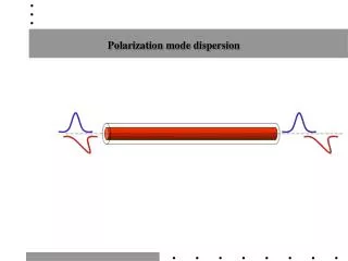
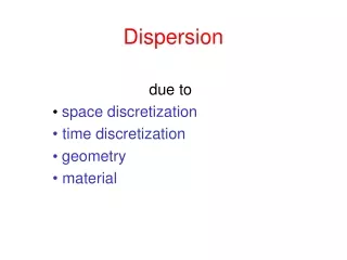
si(t) T so(t) Output pulse L Fibre Dispersion • Data carried in an optical fibre consists of pulses of light energy • consists of a large number of frequencies travelling at a given rate. • There is a limit to the highest data rate (frequency) that can be • sent down a fibre and be expected to emerge intact at the output. • This is because of a phenomenon known as Dispersion (pulse • spreading), which limits the "Bandwidth” of the fibre. Many modes • Cause of Dispersion: • Chromatic (Intramodal) Dispersion • Modal (Intermodal) Dispersion
Definitions Group velocity Group delay Dispersion
Group and Phase Velocity The formation of a wave packet from the combination of two waves with nearly equal frequencies. The envelope of the wave package or group of waves travels at a group velocity vg.
Chromatic/Intramodal Dispersion • Intramodal dispersion arises due to the propagation delay differences between • the different spectral components of the transmitted signal. • Further it increases with the increase in spectral width of the optical source. • This spectral width is the range of • wavelengths emitted by the optical source. • For example in the case of LED, • it has a large spectral width about • 40 nm since it emits wavelengths • from 830–870 nm with the peak emission wavelength at 850 nm. • In the case of laser diode which has a very narrow spectral width, the spectral width • is about 1 or 2 nm only. • Thus the Intramodal dispersion can be reduced in an optical fiber using single mode • laser diode as an optical source. Laser = 1-2 nm = R.M.S Spectral width LED (many modes) = 40 nm wavelength
Chromatic/Intramodal Dispersion • Main causes: • Material dispersion • Waveguide dispersion
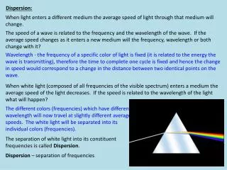
Material Dispersion • This dispersion arises due to the different group velocities of the various spectral components launched into the fiber. • A material is said to exhibit material dispersion when • Pulse spreading occurs even when different wavelengths follow the same path. • Sometimes referred to as Chromatic dispersion , since this is the same effect by which a prism spreads out a spectrum. In a prism, material dispersion (a wavelength-dependent refractive index) causes different colors to refract at different angles, splitting white light into a rainbow
RMS pulse broadening Where material dispersion coefficient: 175 100 Dmat 0 -100 0.8 1.0 1.2 1.4 1.6 1.7 Material Dispersion Refractive index of silica is frequency dependent. Thus different frequency (wavelength) components travel at different speed 2nd window Note: Negative sign, indicates that low wavelength components arrives before higher wavelength components.
Waveguide Dispersion • This results from variation of the group velocity with wavelength for • a particular mode. • Signal in the cladding travels with a different velocity than the signal in the core • The amount of waveguide dispersion depends on the fiber design like core radius and the size of the fiber. • This can usually be ignored in multimode fibres, since it is very • small compared with material dispersion. • However it is significant in monomode fibres.
175 Waveguide dispersion 100 Dmat 0 Total dispersion Material dispersion -100 0.8 1.0 1.2 1.4 1.6 1.7 Waveguide Dispersion • In the case of single mode fibers, waveguide dispersion • arises when
Modal (Intermodal) Dispersion • Result of different values of the group delay for each individual mode at a single frequency. • This variation in the group velocities of the different modes results in a group delay spread of intermodal distortion. • This distortion mechanism is eliminated by single-mode operation, but it is important in multimode fibers.
1 Cladding n2 2 Core n1 c Modal (Intermodal) Dispersion • Lower order modes travel almost parallel to the centre line of the fibre cover the shortest distance, thus reaching the end of fibre sooner. • The higher order modes (more zig-zag rays) take a longer route • as they pass along the fibre and so reach the end of the fibre later. • Mainly in multimode fibers
The time taken for ray 1 to propagate a length of fibre L gives the minimum delay time: The time taken for the ray to propagate a length of fibre L gives the maximum delay time: Since The delay difference Since relative refractive index difference Thus Modal Dispersion - SIMMF
Thus For 1, and Modal Dispersion - SIMMF For a rectangular input pulse, the RMS pulse broadening due to modal dispersion at the output of the fibre is: Total dispersion = chromatic dispersion + modal dispersion
Modal Dispersion - GIMMF The delay difference the RMS pulse broadening
Modal Dispersion - GIMMF Intermodal dispersion in multimode fibers is minimized with the use of graded index fibers. Hence multimode graded index fibers show substantial bandwidth improvement over multimode step index fibers. The fiber has a parabolic index profile with a maximum at the core axis.
Modal Dispersion - GIMMF • It may be observed that apart from the axial ray the meridional rays follow sinusoidal trajectories of different path lengths which results from the index grading. • The longer sinusoidal paths are compensated for by the higher speeds in the lower index medium away from the axis. • The ray that travels along the axial ray is exclusively in the high index region at the core axis, and at the lowest speed. • Thus there is an equalization of the transmission times of the various trajectories and the graded index profile reduces the disparity in the mode transit times. • Thus the delay difference between the fastest and slowest modes are reduced for graded index fiber.
Bandwidth Limitations • Maximum channel bandwidth B: • For non-return-to-zero (NRZ) data format: B = BT /2 • For return-to-zero (RZ) data format: B = BT • Where the maximum bit rate BT = 1/T, and T = bit duration. • For zero pulse overlap at the output of the fibre BT <= 1/2 • where is the pulse width. • For MMSF: BT (max) = 1/2Ts • For a Gaussian shape pulse:BT 0.2/rms • where rms is the RMS pulse width. • For MMSF: BT (max) =0.2/ modal • or • BT (max) =0.2/ T Total dispersion
Bandwidth Distance Product (BDP) The BDP is the bandwidth of a kilometer of fibre and is a constant for any particular type of fibre. Bopt * L = BT * L (MHzkm) For example, A multimode fibre has a BDP of 20 MHz.km, then:- - 1 km of the fibre would have a bandwidth of 20 MHz - 2 km of the fibre would have a bandwidth of 10 MHz • Typical B.D.P. for different types of fibres are: • Multimode 6 - 25 MHz.km • Single Mode 500 - 1500 MHz.km • Graded Index 100 - 1000 MHZ.km
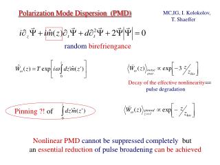
Birefringence in single-mode fibers • Because of asymmetries the refractive indices for the two degenerate modes (vertical & horizontal polarizations) are different. This difference is referred to as birefringence, : Optical Fiber communications, 3rd ed.,G.Keiser,McGrawHill, 2000
Birefringence in single-mode fibers • The effects of fiber birefringence on the polarization states of an optical signal are another source of pulse broadening. • Results from intrinsic factors such as geometric irregularities of the fiber core or internal stresses on it. • External factors such as bending, twisting or pinching of the fiber can also lead to birefringence. • All these mechanisms exist to some extent in the fiber, there will be a varying birefringence along its length.
Fiber Beat Length • In general, a linearly polarized mode is a combination of both of the degenerate modes. As the modal wave travels along the fiber, the difference in the refractive indices would change the phase difference between these two components & thereby the state of the polarization of the mode. However after certain length referred to as fiber beat length, the modal wave will produce its original state of polarization. This length is simply given by: