Download
1 / 19
230 likes | 617 Views
INTRODUCTION TO PROFESSIONAL WHEEL ALIGNMENT. GENERAL. ‘’VEHICLE ATTITUDE’’ is taken to mean the geometric condition of all the parts which contribute to the determination of the position of the wheels when moving on the ground, either in a straight line or on bends.

E N D
GENERAL • ‘’VEHICLE ATTITUDE’’ is taken to mean the geometric condition of all the parts which contribute to the determination of the position of the wheels when moving on the ground, either in a straight line or on bends. • This geometric attitude can be checked only in a static state, i.e. when the vehicle is stationary, with the wheels in the straight travel position and in the turning position.
VEHICLE GEOMETRY BASIC CONDITIONThe vehicle must satisfy certain set conditions of symmetry and perpendicularity in the axes
BEFORE STARTING TO CHECK THE GEOMETRIC ATTITUDE OF THE VEHICLE • Locate and eliminate any play on the suspension and steering rods • Position the vehicle on a level surface • Carefully check the tyre pressures • Respect and take into account the specified load conditions • Respect and take into account the load distribution • Check to see if there is any irregular give on the elastic parts of the suspension or stiffening of the joints.
To absorb the bumps, more confort for passengers. to avoid subjecting the mechanical parts to excessive wear. To ensure that the tires are in constant contact with the ground to achieve good road-holding and more safety. SUSPENSION SYSTEMSTHE WORD SUSPENSION IS USED TO DESCRIBE THE TOTALITY OF ELASTIC PARTS THAT CONNECT THE WHEELS TO THE CHASSIS OR UNITIZED BODY SUSPENSION SYSTEMS HAVE THE FOLLOWING FUNCTIONS:
WHEEL ANGLES KINGPIN ANGLES Wheel toe-in Wheel camber angle Wheel toe-out on turns (only in front) Longitudinal caster angle or, in brief form "caster angle“ Transverse king pin inclination or, in brief form "king pin inclination CHARACTERISTIC ANGLES
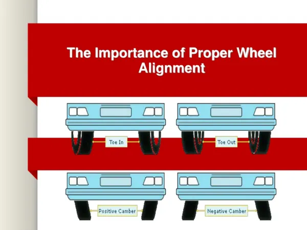
WHEEL TOE-IN AND TOE-OUT • Wheel toe-in is the angle formed by the center line of the wheel and the longitudinal axis of the vehicle, looking at the vehicle from above. • The sum of the toe-in values for each single wheel (α+β) gives the total toe-in value • Parallel Wheels = 0 toe POSITIVE NEGATIVE
EFFECT OF LOAD ON TOE-IN/OUT 1. When measuring the toe-in/out, it is advised to refer to the manufacturers' specifications and check whether the toe-in/out tendency is positive or negative by moving the vehicle up and down in a vertical direction; after this, apply the specified data and tolerances according to the average use and load conditions. DYNAMIC EFFECTS ON TOE-IN/OUT The front wheels or rear non-drive wheels have a TOE-IN position when the vehicle is stationary The front wheels or rear drive wheels have a TOE-OUT position when the vehicle is stationary
IRREGULAR TYRE WEAR TOE The wear caused on a tyre with excessive toe-in or toe-out, has certain typical characteristics: • A wheel with excessive toe-in tends to consume the outside of the wheel • A wheel with excessive toe-out tends to consume the inside of the wheel
CAMBER ANGLE The wheel camber angle is the angle, measured in degrees, between the center line of the wheel and the perpendicular to the ground, looking at the vehicle from the front. POSITIVE NEGATIVE
EFFECTS • With the introduction of independent-arm suspension, the wheel camber angle tends towards a value very close to zero under the most common use, the camber angles of the wheels will tend to change as the vehicle is jolted about. • The independent-arm suspension being preferred to rigid-axle suspension. The benefits of this effect are most apparent on bends, where the compression of the suspension on the outer wheel on the bend, caused by centrifugal force, produces a negative camber on the wheel and more stability
TOE-IN ON BENDS • The steering geometry is defined as the toe-out position taken by the during a turn; it is expressed by the two values, in degrees, through which the wheels turn (considering one fixed value on the turn of 20 grade, set by convention). EXAMPLE : The outer wheel on the turn turns through 20 and the inner wheel through 23 or, vice versa, the inner wheel on the turn turns through 20 and the outer wheel through 17. In the example it can be seen that the toe-in on the basis of 20 is 3, taken from the difference (20-17), or from the difference (23-20)
TOE-IN ON BENDS • The ideal condition is the following: The wheels, when travelling in a straight line, must have a toe-out value near to 0 degrees, and as soon as they start to turn the toe-out value must increase progressively, becoming more accentuated with the increase in the angle of the turn.
CASTER ANGLE 1. Steering axis longitudinal inclination 2. Vertical 3. Steering axis 4. Projection of the steering axis 5. Contact point between wheel and ground • The CASTER ANGLE is the angle, measured in degrees, formed between the steering axis and the perpendicular to the ground, looking at the vehicle from the side • The caster angle is zero when the steering axis is perfectly vertical POSITIVE NEGATIVE 1. Direction of travel
EFFECTS The CASTER ANGLE given to the steering axis creates two very important phenomena for the ride of the vehicle: • The first is related to stability, in maintaining the straight line travel of the vehicle, with the relative return of the steering after steering round a bend. • The second is the tilt of wheel which occurs during steering, and which is observed by the inclination of the wheel when being turned
KINGPIN INCLINATION • The KINGPIN INCLINATION is the angle, measured in degrees, that forms the line passing through the steering axis and the perpendicular to the ground, looking at the vehicle from the front 1. Kingpin inclination 2. Steering axis (Kingpin axis)
KINGPIN INCLINATION The Kingpin inclination is defined positive when the projection of the kingpin axis goes near to the wheel at its point of contact with the ground (inclined in the opposite way to the wheel camber) ; it is difficult, if not impossible, to have a negative kingpin inclination POSITIVE V. Kingpin Inclination B. Nearly null EFFECTS The king pin inclination angle, amongst other things, creates the phenomenon of the return of wheels to the straight position after a steering operation
THANKS FOR YOUR ATTENTION WWW.FASEP.IT FASEP 2000 s.r.l Via Faentina, 96 – 50030 Ronta (Firenze) Italy Tel. +39 055 8403126 – Fax +39 055 8403354 E-mail: info@fasep.it