Download
1 / 26
260 likes | 404 Views
Column Operating Pressure and Condense Type. ~Reflux drum pressure, P D , is between 0 and 415 psia (2.86 MPa) at a minimum temperature of 120 F (49 C) (corresponding to the use of water as the coolant in the condenser). ~A condenser pressure drop of 0 to 2 psi (0 to 14

E N D
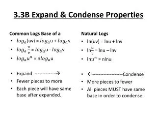
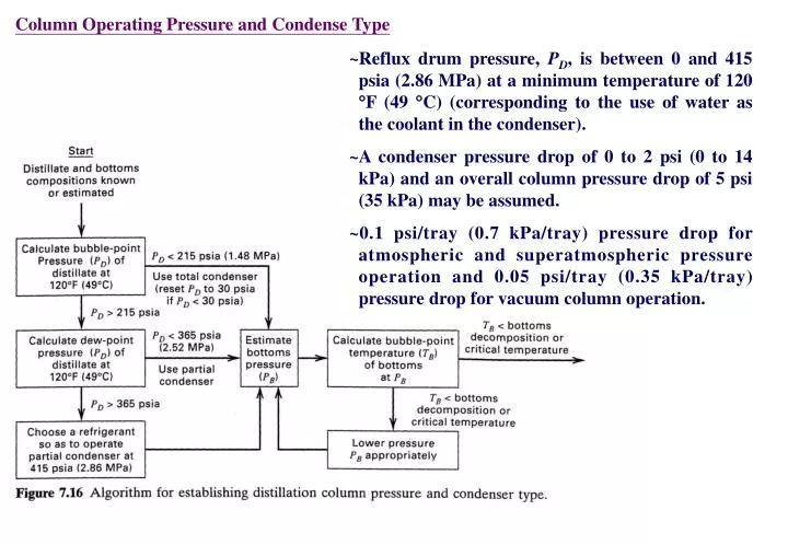
Column Operating Pressure and Condense Type ~Reflux drum pressure, PD, is between 0 and 415 psia (2.86 MPa) at a minimum temperature of 120 F (49 C) (corresponding to the use of water as the coolant in the condenser). ~A condenser pressure drop of 0 to 2 psi (0 to 14 kPa) and an overall column pressure drop of 5 psi (35 kPa) may be assumed. ~0.1 psi/tray (0.7 kPa/tray) pressure drop for atmospheric and superatmospheric pressure operation and 0.05 psi/tray (0.35 kPa/tray) pressure drop for vacuum column operation.
~A total condenser is recommended for reflux drum pressures to 215 psia (1.48 MPa). ~A partial condenser is appropriate from 215 psia to 365 psia (2.52 MPa). However, a partial condenser can be used below 215 psia when a vapor distillate is desired. ~A mixed condenser can provide both vapor and liquid distillates. ~A refrigerant is used as condenser coolant if pressure tends to exceed 365 psia. When a partial condenser is specified, the McCabe-Thiele staircase construction for the case of a total condenser must be modified to account for the fact that the first equilibrium stage, counted down from the top, is the partial condenser. This is based on the assumption that the liquid reflux leaving the reflux drum is in equilibrium with the vapor distillate.
Example 7.2 One thousand kilomoles per hour of a feed containing 30 mol% n-hexane and 70% n-octane is to be distillated in a column consisting of a partial reboiler, one equilibrium (theoretical) plate, and a partial condenser, all operating at 1 atm (101.3 kPa). Thus, hexane is the light key and octane is the heavy key. The feed, a bubble-point liquid, is fed to the reboiler, from which a liquid bottoms product is continuously withdrawn. Bubble-point reflux is returned from the partial condenser to the plate. The vapor distillate, in equilibrium with the reflux, contains 80 mol% hexane, and the reflux ratio, L/D, is 2. Assume that the partial reboiler, plate and partial condenser each function as equilibrium stages. (a)Using the McCabe-Thiele method, calculate the bottoms composition and kilomoles per hour of distillate produced. (b)If the relative volatility is assumed constant at a value of 5 over the composition range (the relative volatility actually varies from approximately 4.3 at the reboiler to 6.0 at the condenser), calculate the bottoms composition analytically.
Solution slope=L/V=L/(L+D)=2/3 (a) Graphical solution D=248 kmol/h xB=0.135 (b) Analytical solution
Example 7.3 Consider Example 7.2. (a) Solve it graphically, assuming that the feed is introduced on plate 1, rather than into the reboiler. (b) Determine the minimum number of stages required to carry out the separation. (c) Determine the minimum reflux ratio. Solution slope=L/V=L/(L+D)=2/3 (b) (a) slightly more than two stages by trial and error, xB=0.07 (c)
Reboiler Type For small laboratory and pilot-plant-size columns, the reboiler consists of a reservoir of liquid located just below the bottom plate to which heat is supplied from (1) a jacket or mantle that is heated by an electrical current or by condensing steam, or (2) tubes that pass through the liquid reservoir carrying condensing steam. Both of these types of reboilers have limited heat transfer surface and are not suitable for industrial applications. ~For plant-size distillation columns, the reboiler is usually an external heat exchanger of either kettle or vertical thermosyphon type. Both can provide the amount of heat transfer surface required for large installations. ~In the kettle reboiler, liquid leaving the sump (reservoir) at the bottom of the column enters the kettle, where is partially vaporized by the transfer of heat from tubes carrying condensing steam or some other heating medium. The bottoms product liquid leaving the reboiler is assumed to be in equilibrium with vapor returning to the bottom tray of the column. Thus the kettle reboiler is a partial reboiler equivalent to one equilibrium stage. The kettle reboiler is sometimes located in the bottom of the column to avoid piping.
The vertical thermosyphon reboiler may be of the type shown in Figure 7.21b or 7.21c. In the former, both the bottoms product and the reboiler feed are withdrawn from the column bottom sump. Circulation through the tubes of the reboiler occurs because of the difference in static heads of the supply liquid and the column of partially vaporized fluid flowing through the reboiler tubes. The partial vaporization provides enrichment of the exiting vapor in the more volatile component. However, the exiting liquid is then mixed with liquid leaving the bottom tray, which contains a higher percentage of the more volatile component. The result is that this type of reboiler arrangement provides only a fraction of an equilibrium stage. A more complex and less common vertical thermosyphon reboiler is that of Figure 7.21c, where the reboiler liquid is withdrawn from the downcomer of the bottom tray. Partially vaporized liquid is returned to the column, where the bottoms product from the bottom sump is withdrawn. This type of reboiler does function as an equilibrium stage.
Kettle reboiler are common, but thermosyphon reboilers are favored when (1) The bottoms product contains thermally sensitive compounds, (2) Bottoms pressure is high, (3) Only a small T is available for heat transfer, and (4) Heavy fouling occurs. Horizontal thermosyphon reboilers are sometimes used in place of the vertical types when only small static heads are needed for circulation, surface area requirement is very large, and/or when frequent cleaning of the tubes is anticipated. A pump may be added for either thermosyphon type to improve circulation. Liquid residence time in the column bottom sump should be at least 1 minute and perhaps as much as 5 minutes or more.
Condenser and Reboiler Duties An energy balance for the entire column gives For a total condenser, For a partial condenser, For a partial reboiler, Hvap=average molar heat of vaporization of the two components being separated. When the feed is at the bubble-point and a total condenser is used, the following equation is obtained. When the feed is partially vaporized and a total condenser is used, the heat required by the reboiler is less than the condenser duty and is given by
If saturated steam is the heating medium for the reboiler, the steam rate required is given by an energy balance: ms=mass flow rate of steam QR=reboiler duty (rate of heat transfer) Ms=molecular weight of steam Hsvap=molar enthalpy of vaporization of steam The cooling water rate for the condenser is mcw=mass flow rate of cooling water Qc=condenser duty (rate of heat transfer) Cp,H2O=specific heat of water Tout, Tin=temperature of cooling water of and into the condenser, respectively
Optimal Reflux Ratio ~An industrial distillation column must be operated between the two limiting conditions of minimum reflux and total reflux. ~As shown in Table 7.3, for a typical case adapted from Peter and Timmerhaus, as the reflux ratio is increased from the minimum value, the number of plates decreases, the column diameter increases, and the reboiler steam and condenser cooling water requirements increase.
~When the annualized fixed investment costs for the column, condense, reflux drum, reflux pump, and reboiler are added to the annual cost of steam and cooling water, an optimal reflux ratio is established, as shown in Figure 7.22. ~For this example the optimal R/Rmin is 1.1. ~The data in Table 7.3 show that although the condenser and reboiler duties are almost identical for a given reflux ratio, the annual cost of steam for the reboiler is almost eight times that of cooling water for the condenser. The total annual cost is dominated by the cost of steam except at the minimum-reflux condition. At the optimal reflux ratio, the cost of steam is 70% of the total annualized cost. ~Because the cost of steam is dominant, the optimal reflux ratio is sensitive to the steam cost. For example, at the extreme of zero cost for steam, the optimal R/Rmin for this example is shifted from 1.1 to 1.32. This example assumes that the heat moved by cooling water in the condenser has no value. The range of optimal ratio of reflux to minimum reflux often is from 1.05 to 1.50, with the lower value applying to difficult separation (e.g., =1.2) and the higher value applying to an easy separation (e.g., =5).
Large Number of Stages 1.Separate plots of expanded scales and/or larger dimensions are used for stepping off stages at the ends of the y-x diagram. For example, the additional plots might cover just the regions (1) 0.95 to 1.0 and (2) 0 to 0.05. 2.As shown in Figure 7.23, a plot based on logarithmic coordinates is used for the low (bottoms) end of the y-x diagram, while for the high (distillate) end, the log-log graph is returned upside down and rotated 90. 3.The stages at the two ends are computed algebraically. 4.If the equilibrium data are given in analytical form, commercially available McCabe- Thiele computer programs can be used. 5.The stages are determined by combining the McCabe-Thiele graphical construction, for a suitable region in the middle, with the Kremser equations for the low and/or high ends, where absorption and stripping factors are almost constant.
Example 7.4 Repeat part (c) of Example 7.1 for distillate and bottoms purities of 99.9 and 0.1 mol%, respectively, using a reflux ratio of 1.88, which is about 30% higher than the minimum reflux of 1.44 for these new purities. Solution Figure 7.24 shows the McCable-Thiele construction for the region of x from 0.028 to 0.956, where the stages have been stepped off in two direction starting from the feed stage. In this middle region, nine stage are stepped off above the feed stage and eight below the feed stage, for a total of 18 stages, including the feed stage. The Kremser equation can now be applied to determine the remaining stages needed to achieve the desired high purities for the distillate and bottoms.
Additional stages for the rectifying section NR=additional equilibrium stages for the rectifying section. For that section, which is like an absorption section, it is best to apply Eq. (*) to toluene, the heavy key. Because =2.52 at the top of the column, where Kbenzene is close to one, take Ktoluene=1/2.52=0.408. Since R=1.88, L/V=R/(R+1)=0.653. Therefore, the absorption factor for toluene is Atoluene=L/VKtoluene=0.653/0.408=1.60 which is assumed to remain constant in the uppermost part of the rectifying section.
Additional stages for the stripping section NS=additional equilibrium stages for the stripping section. =absorption factor in the stripping section= Because benzene is being stripped in the stripping section, it is best to apply Eq. (**) to benzene. At the bottom of the column, where Ktoluene is approximately 1.0, =2.26, and thereforeKbenzene=2.26.
Use of Murphree Efficiency EMV is the Murphree vapor efficiency for stage n, where n+1 is the stage below and yn* is the composition in the hypothetical vapor phase in equilibrium with the liquid composition leaving stage n. Note: Values of EMV can be less than or somewhat more than 100%. Values of EMV are equal for the two components of a binary mixture.
Multiple Feeds, Side Streams, and Open Steam ~In the absence of side stream Ls, this arrangement has no effect on the material balance associated with the rectifying section of the column above the upper feed point, F1. ~The section of column between the upper feed point and the lower feed point F2 (in the absence of feed F) is represented by an operating line of slope L’/V’, this line intersecting the rectifying-section operating line.
~In Figure 7.27 (a), Feed F1 is a dew-point vapor, while feed F2 is a bubble-point liquid. Thus, between the two feed points, the molar vapor flow rate is V’=V-F1 and =L’+F2=L+F2. ~In Figure 7.27 (b), a saturated liquid side stream of composition xs and molar flow rate Ls is withdrawn from the rectifying section. In the section of stages between the side stream-withdrawal stage and the feed stage, L’=L-Ls, while V’=V. ~In Figure 7.27 (c), open steam (y=0) can be used if one of the components in the mixture is water, or if water can form a second phase, thereby reducing the boiling point.
Example 7.5 A complex distillation column, equipped with a partial reboiler and total condenser, and operating at steady state with a saturated liquid feed, has a liquid side stream draw-off in the enriching (rectifying) section. Making the usual simplifying assumptions of the McCabe-Thiele method: (a) Derive an equation for the two operating lines in the enriching section. (b) Find the point of intersection of these operating lines. (c) Find the intersection of the operating line between F and Ls with diagonal. (d) Show the construction on a y-x diagram. Solution (a)
(b) (c)
Estimation of Stage Efficiency ~Methods for estimating the stage efficiency for binary distillation are analogous to those for absorption and stripping. ~The efficiency is a complex function of tray design, fluid properties, and flow patterns. ~In hydrocarbon absorption and stripping, the liquid phase is often rich in heavy components so that liquid viscosity is high and mass transfer rates are relatively low. This leads to low stage efficiencies, usually less than 50%. ~For binary distillation, particularly of close-boiling mixtures, liquid viscosity is low, with the result that stage efficiencies, for well-designed trays and optimal operating conditions, are often higher than 70% and can be even higher than 100% for large-diameter columns where a crossflow effect is present.
Performance Data ~As discussed in AIChE Equipment Testing Procedure, performance data for an industrial distillation column are best obtained at conditions of total reflux (no feed or products) so as to avoid possible column-feed fluctuation, simplify location of the operating line, and avoid discrepancies between feed and feed-tray compositions. ~As shown by Williams, Stigger, and Nichols, efficiency measured at total reflux can differ markedly from that at design reflux ratio. Ideally, the column is operated in the range of 50% to 85% of flooding. ~If liquid samples are taken from the top and bottom of the column, the overall plate efficiency, Eo, can be determined from Eo=Nt/Na, where the number of theoretical stages required is determined by applying the McCabe-Thiele method at total reflux. ~If liquid samples are taken from the downcomers of intermediate trays, Murphree vapor efficiencies, EMV, can be determined using . ~If liquid samples are withdrawn from different points on one tray, can be applied to obtain point efficiencies, EOV.
Table 7.4, from Gerster et al., lists plant data, obtained from Eastman Kodak Company in Rochester, New York, for the distillation at total reflux of a methylene chloride (MC)-ethylene chloride (EC) mixture in a 5.5-ft-diameter column containing 60 bubble cap trays on 18-in. tray spacing and operating at 85% of flooding at total reflux.
Example 7.6 Using the performance data of Table 7.4, estimate: (a) the overall tray efficiency for the section of trays from 33 to 29 and (b) the Murphree vapor efficiency for tray 32. Assume the following values for relative volatility:
Solution (b) (a) At total reflux conditions, passing vapor and liquid streams have the same composition. That is, the operating line is 45 line. Using this together with the above performance data and the equilibrium curve is Figure 7.30, we obtain for methylene chloride, with trays counted from the bottom up: The x--y data are plotted in Figure 7.30. Four theoretical stage are stepped off from x33=0.898 to x29=0.0464 for total reflux. Since the actual number of stage is also 4, the overall stage efficiency from (6-21) is 100%