Download
1 / 20
200 likes | 384 Views
Summary of mini-review of the FE architecture for OT straws upgrade. Antonio Pellegrino on behalf of the OT group CERN, Electronis Upgrade Meeting 11-04-2013. intro (summary of presentations, short!) referee report (main body of this talk) comments issues recommendations

E N D
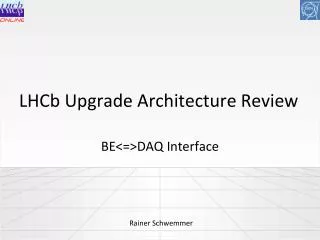
Summary of mini-review of the FE architecture for OT straws upgrade Antonio Pellegrino on behalf of the OT group CERN, Electronis Upgrade Meeting 11-04-2013 • intro (summary of presentations, short!) • referee report (main body of this talk) • comments • issues • recommendations • some answers (few!) and outlook
People & Subject “Mini-review” : ARCHITECTURE of the Upgraded FE for OT straw tubes Nikhef, March 6 2013 Reviewers: • CsabaSoos (CERN PH-ESE-BE and Alice) • Federico Alessio (CERN PH-LBC and LHCb) • RuudKluit (Group leader of Electronics Technology, Nikhef) • Ken Wyllie (LHCb electronics coordinator, chairman) Representing OT: • Christian Faerber (Heidelberg) • Stefan Swientek (Dortmund) • WilcoVink (Nikhef) • Tom Sluijk (Nikhef) • Antonio Pellegrino (Nikhef)
Ken’s guidelines for the mini-review Documentation and presentations should be prepared covering the following topics: • Overall requirements of the sub-detector system. • How the sub-detector plans to implement the components of the general LHCb architecture in their specific environment (see below). • The boundary conditions used for the design, for example detector hit-occupancy and radiation environment. • Results from prototyping. • Any missing information that is required to complete their design. • Preparation of specifications documents for designs. • Manpower. The following items of the proposed architecture should be described: • Analog front-end • Digital processing (digitisation, data-compression, buffering, formatting) • Data transmission • Timing and Fast Control • Experiment Control System • Power distribution • Infrastructure • System robustness (eg radiation, detector data, synchronisation....)
Review Agenda just as guideline: order can be swapped + interruption for discussion • FE Architecture • Nikhef FE Design (Wilco + Tom) • Heidelberg FE Design (Christian) • Coffee + visit lab • Prototypes, Production, Installation etc. • Prototypes (Wilco) • No of data links, TFC+ECS distr., power, etc. (Tom) • Lunch • Irradiation Tests • Irradiation Arria (Christian) • Irradiation Actel (Antonio)
Agenda mini-review ARCHITECTURE of the Upgraded FE OT straw tubes https://indico.cern.ch/conferenceDisplay.py?confId=239292 Will not give you an exhaustive summary of presentations, only a couple of slides, then concentrate on items from referees report
Straw-Tubes Upgrade Overview OUTER TRACKER CENTRAL TRACKER OUTER TRACKER OUTER TRACKER INNER TRACKER 2) “Old”+“New” straw-tube modules + Si IT 1) “Old” straw-tube modules + SciFi CT upgrade of the straw-tubes modules FE Electronics required in both tracking upgrade scenarios presented in the Framework TDR, only production quantities change (in a 4/9 ratio) Of course, if somebody would be bold enough to replace the whole straw-tube surface by SciFi...
Straw Front-End Upgrade Overview We have 432 of these objects (FE Boxes in OT) • 36 per C-Frame (12 C-Frames) GOL/AUX Board (and ASIC) needs replacement LVcable HV cable OTIS Boards (and ASIC) need replacement HV and ASDBLR Boards may remain unchanged and try to keep most of infrastructure unchanged
Upgraded FE Architecture • 432 Total: • 3888 GBT’s • 432 TFC Master GBT’s (bi-dir) • 3456 Data GBT’s • 2160 SCA’s • 432 Front end boxes, each: • 1 master GBT / power board • 1 Master GBT • TFC distribution • 1 SCA • Optical RxTx • CERN SM01C DC/DC conv. • 4 TDC boards • Actel Proasic3E • 2 data GBT’s (112b wide bus) • 1 SCA • 8 ASDBLR boards
TDC, zero-supp, data & all that... 32 channel TDC Zero-supp 32 stages Fifo Readout GBT Hit 3*PLL Control / Monitoring TFC/ECS Actel FPGA Data Format (9 channels hit): GBT 27 0 16 bits Hit pattern channel (0-15) 4 bits BX cnt 8 bits Status Data 5 bits Data 5 bits Data 16 bits Hit pattern channel(16-31) 5 bits Data 5 bits Data 5 bits Data 5 bits Data 5 bits Data 5 bits Padded ‘0’ s 5 bits Data Max 8 words when all channels are hit
Example Data Format E.g. N.B. using buffering, but data aligned on 28-bits boundaries
Prototypes, test-systems, etc. • Prototype combined TDC board and GBT master Board • ¼ Front end box: 32 TDC channel inputs 2 GBT data outputs • Two StratixIV dev. Board as • Small TFC: BcntRst, Sync, CLk’s • Simple DAQ: TDC readout, based on GBT wide bus format • DDR3 Data buffer for TDC characterisation • Two GbE data readout and control/monitoring, with host PC • OTTO (Outer Tracker TDC to Optical) • Actel 32 channel 5 bits TDC’s • Optical components (SOL40, TELL40) • To be done • Include Wide bus format GBT optical connection in datapath • Use AMC40/TP Back end for: • miniDAQ Data input • TFC and Ecs
Irradiation Tests At worst location, estimate ~7.2 krad for 50 fb-1 (no safety factor) Lots of results from Actel and Altera irradiations were presented
Referees Report - 1 “For further development it will be useful if the decision on Straws versus Sci Fibers can be made soon (2013). It has significant impact on the electronics design, and valuable design effort is lost if the decisions are being postponed.” “Note: it is not excluded that the straw tubes are entirely replaced by scintillating fibers leading to a completely new architecture. Decision should be taken soon as it has a large impact on the overall system.” OT Comment: agreed!
Referees Report - 2 “Both solutions and radiation tests presented during the workshop seem feasible, considering the radiation dose expected at the location of the electronics. If however, radiation expectancy will go above 30krad, the FPGA choice does not seem to be recommended. Reconfiguration of FPGA and even automated reprogramming of FPGAs is not recommended. Continuous tuning and reprogramming of detector system parts is not considered to be a reliable solution. Possibly more rad-hard FPGA`s will come out soon in the future. Search for other experience (Space Req.) or investigate the newer Actel FPGA family with higher priority.” OT Comment: agreed, will do!
Referees Report - 3 “Investigate to reduce nr. of GBT’s used (power & timing path) Power budget should be verified and discussed.” OT Comments: • we can reduce the no. of data GBTx from 8 to 4 per FE, accepting resulting occupancy limitations • power budget has been checked, present demi-water cooling plant designed for 15 kW, with a dimensioning figure of 22.5 kW (1.5 safety factor) • see next slides for comment on GBT as TFC fan-out
Referees Report - 4 “Reconsider the clock fan-out and timing path, transmission of TFC commands now thru several GBT’s. An alternative FPGA implementation should be investigated. - Clock fan-out using GBT ? Many clock signals to TDC. Is it feasible/needed ? Chaining chips and thus PLLs may lead to locking issues, more jitter and/or phase difficulties. - It is not clear how to fan out TFC signals? Using GBT as fan-out ? Use FPGA (Actel) to convert SLVS to LVDS ? ----> Using a slave GBT to drive clocks for the TDC FPGA is a good solution, considering that the GBT has already all the features that the FPGA needs. However, fanning out TFC commands is an issue. Repeating 4 times the TFC commands can be done, but it should be avoided as much as possible, to not have to maintain many firmware’s. A solution should be investigated (another FPGA(Actel) as suggested during the review?).” OT Comments: agreed, this part needs further thinking. Would like to know if other groups have this issue and how they are going to tackle it
Referees Report - 5 “Simulation of the data path with expected occupancies and proposed buffer sizes should be demonstrated. The nr. of BXID bits in the data should be reconsidered (increase). - 4 BXIDs is too few. I feel 16 clock cycles at 40 MHz is too little margin for the Readout Board. In an efficient packing algorithm, the Readout Boards must find each data word without ambiguities and it will use the BXID to check for successive events and the size (which can be deducated from the hit pattern) to define the boundaries. We should aim at transmitting 12 bits or as much as possible out of the 12 BXIDs (8 minimum?). - ZS and NZS could be sent more flexibly, there is no need to develop two scenarios and choose among them. Usage of buffer should be more flexible, buffer should be used to absorb NZS data transmission or many consecutive high occupancies events. In the protocol presented in the review, the buffer is basically never exploited. Designing the system for 100% occupancy it is a little too safe.” OT Comments: • simulations started, will be finalized • BXID will be enlarged (at the expenses of data bandwidth) • ZS/NZS TFC commands already handled (misunderstood by ref. ?) • buffering is exploited, only limitation is 28-bits alignment (misunderstood by ref. ?)
Referees Report - 6 “Demonstrate the reliability of the final optical components, including the patch requirements. Power budget including radiation penalty should be calculated. Reliability of VCSELs is a concern (both cases). However, Versatile Link uses already packaged components. Packaging of VCSEL arrays require delicate handling. Production quality and reliability should be verified and demonstrated. Decide on optical solution in 2013; VCSEL array/VTTx opt. link. Focus on one design solution gives better view on the system design (integration in mechanics, cable routing, power, PCB use, etc.).” OT Comments: agreed on all points, will do!
Referees Report - 7 • Be prepared for labor intensive installation of the detector components. • A final design review needs to be done after a conceptual prototype can be demonstrated. OT Comments: agreed on both points, will try to prepare for both!
My own (biased) view • I think the design is proceeding well, and referees agreed that the concept is sound (“the present system is eexpected to perform within requirements”) • clearly some specific issues (rad. hardness, TFC fan-outs, power budget, optical components, etc.) emerged during the review that need to be addressed before finalizing the design • urgency of decision between SciFi and straws was clearly pointed out as an important factor • manpower restrictions were noted by the referees (“Once this detector decision is made, the manpower situation will have to be carefully assessed. The current manpower is below the level that was required to construct the existing OT system”)