Download
1 / 47
480 likes | 666 Views
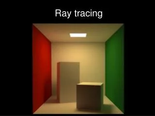
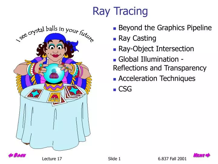
Ray Tracing. Beyond the Graphics Pipeline Ray Casting Ray-Object Intersection Global Illumination - Reflections and Transparency Acceleration Techniques CSG. Graphics Pipeline Review. Properties of the Graphics Pipeline Primitives are processed one at a time

E N D
Ray Tracing • Beyond the Graphics Pipeline • Ray Casting • Ray-Object Intersection • Global Illumination - Reflections and Transparency • Acceleration Techniques • CSG Slide 1
Graphics Pipeline Review • Properties of the Graphics Pipeline • Primitives are processed one at a time • All analytic processing early on • Sampling occurs late • Minimal state required (immediate mode rendering) • Processing is forward-mapping Slide 2
Alternative Approaches There are other ways to compute views of scenes defined by geometric primitives. One of the most common is ray-casting. Ray-casting searches along lines of sight, or rays, to determine the primitive that is visible along it. • Properties of ray-casting: • Go through all primitives at each pixel • Sample first • Analytic processing afterwards • Requires a display list Slide 3
Ray Casting Outline • For every pixel construct a ray from the eye through the pixel. • For every object in the scene • Find “time” of intersection with the ray closest (and in front of) the eye • Compute normal at point of intersection • Compute color for pixel based on point and normal at intersection closest to the eye (e.g. by Phong illumination model). t0 Slide 4
First Step - From Pixels to Rays Slide 5
Java Version // Compute viewing transformation that maps a// screen coordinate to a ray directionVector3D look = new Vector3D(lookat.x-eye.x, lookat.y-eye.y, lookat.z-eye.z);Du = Vector3D.normalize(look.cross(up));Dv = Vector3D.normalize(look.cross(Du));float fl = (float)(width / (2*Math.tan((0.5*fov)*Math.PI/180)));Vp = Vector3D.normalize(look);Vp.x = Vp.x*fl - 0.5f*(width*Du.x + height*Dv.x);Vp.y = Vp.y*fl - 0.5f*(width*Du.y + height*Dv.y);Vp.z = Vp.z*fl - 0.5f*(width*Du.z + height*Dv.z); Example use: Vector3D dir = new Vector3D(i*Du.x + j*Dv.x + Vp.x, i*Du.y + j*Dv.y + Vp.y, i*Du.z + j*Dv.z + Vp.z);Ray ray = new Ray(eye, dir); // normalizes dir Slide 6
Object Intersection Intersecting a sphere with a ray: A sphere is defined by its center, s, and its radius r. The intersection of a ray with a sphere can be computed as follows: Slide 7
Early Rejection The performance of ray casting is determined by how efficiently ray object intersections can be determined. Let's rethink the series of computations used to determine the ray-sphere intersection while looking for ways to eliminate unnecessary work. Step 1: Thus, we can test if (v - r) is greater than the closes intersection thus far, tbest. If it is then this intersection cannot be closer. We can use this test to avoid the rest of the intersection calculation. Slide 8
More Trivial Rejections We can even structure the intersection test to avoid even more unnecessary work: Step 2: What if the term, r2 - b2 < 0 Clearly we need to test for this case anyway since it will generate anexception when we calculate the expression: Slide 9
Example Code public boolean intersect(Ray ray) {float dx = center.x - ray.origin.x;float dy = center.y - ray.origin.y;float dz = center.z - ray.origin.z;float v = ray.direction.dot(dx, dy, dz);// Do the following quick check to see if there is even a chance// that an intersection here might be closer than a previous oneif (v - radius > ray.t) return false;// Test if the ray actually intersects the spherefloat t = radSqr + v*v - dx*dx - dy*dy - dz*dz;if (t < 0) return false;// Test if the intersection is in the positive// ray direction and it is the closest so fart = v - ((float) Math.sqrt(t));if ((t > ray.t) || (t < 0)) return false;ray.t = t;ray.object = this;return true; } Slide 10
Global Illumination Early on, in the development of computer graphics, ray-casting was recognized as viable approach to 3-D rendering. However, it was generally dismissed because: Takes no advantage of screen space coherence Requires costly visibility computation Only works for solids Forces per pixel illumination evaluations Not suited for immediate mode rendering It was not until Turner Whitted (1980) recognized that recursive ray casting, which has come to be called ray tracing, could be used to address global illumination that interest in ray tracing became widespread. Slide 11
Recursive Ray-Casting Starting from the viewing position, first compute the visible object along each ray. Then compute the visibility of each light source from the visible surface point, using a new ray. If there is an object between the light source and the object point it is in shadow, and we ignore the illumination from that source. We can also model reflection and refractionsimilarly. Slide 12
Recursive Ray Tracing Illumination Check for shadowing (intersection with object along ray (P,L)) Slide 13
The Ray Tree T3 Viewpoint R2 N2 T1 R3 R1 N3 L1 L2 N1 L3 L1 R1 T1 L2 L3 Eye Ni surface normal Ri reflected ray Li shadow ray Ti transmitted (refracted) ray R2 R3 T3 Slide 14
Refraction Snell’s Law Note that I is the negative of the incoming ray Total internal reflection when the square root is imaginary Slide 15
Rendering Equation • Global illumination computes the more general problem of light transfer between all objects in the scene, including direct and indirect illumination. Rendering equation is the general formulation of the global illumination problem: it describes how the radiance from surface x reflects from the surface x’: • L is the radiance from a point on a surface in a given direction ω • E is the emitted radiance from a point: E is non-zero only if x’ is emissive • V is the visibility term: 1 when the surfaces are unobstructed along the direction ω, 0 otherwise • G is the geometry term, which depends on the geometric relationship between the two surfaces x and x’ • Ray tracing approximates the rendering equation by sampling along rays where the integrand is likely to be large. Slide 16
Designing a Ray Tracer Building a ray tracer is simple. First we start with a convenient vectoralgebra library. class Vector3D { public float x, y, z; // constructors public Vector3D( ) { } public Vector3D(float x, float y, float z); public Vector3D(Vector3D v); // methods public Vector3D to(Vector3D B) // B - this public float dot(Vector3D B); // this with B public float dot(float Bx, float By, float Bz); // B spelled out public static float dot(Vector3D A, Vector3D B); // A dot B public Vector3D cross(Vector3D B); // this with B public Vector3D cross(float Bx, float By, float Bz); // B spelled out public static Vector3D cross(Vector3D A, Vector3D B); // A cross B public float length( ); // of this public static float length(Vector3D A); // of A public void normalize( ); // makes this unit length public static Vector3D normalize(Vector3D A); // makes A unit length public String toString(); // convert to a string } Slide 17
A Ray Object • class Ray { • public static final float MAX_T = Float.MAX_VALUE; • Vector3D origin, direction; • float t; • Renderable object; • public Ray(Vector3D eye, Vector3D dir) { • origin = new Vector3D(eye); • direction = Vector3D.normalize(dir); • } • public boolean trace(Vector objects) { • Enumeration objList = objects.elements(); • t = MAX_T; • object = null; • while (objList.hasMoreElements()) { • Renderable object = (Renderable) objList.nextElement(); • object.intersect(this); • } • return (object != null); • } • // ray.Shade(...) is nicer than ray.object.Shade(ray, ...) • public final Color Shade(Vector lights, Vector objects, Color bgnd) { • return object.Shade(this, lights, objects, bgnd); • } • } Slide 18
Light Source Object // All the public variables here are ugly, but I // wanted Lights and Surfaces to be "friends" class Light { public static final int AMBIENT = 0; public static final int DIRECTIONAL = 1; public static final int POINT = 2; public int lightType; public Vector3D lvec; // the position of a point light or // the direction to a directional light public float ir, ig, ib; // color of the light source public Light(int type, Vector3D v, float r, float g, float b) { lightType = type; ir = r; ig = g; ib = b; if (type != AMBIENT) { lvec = v; if (type == DIRECTIONAL) { lvec.normalize(); } } } } Slide 19
Renderable Interface // An object must implement a Renderable interface in order to// be ray traced. Using this interface it is straightforward// to add new objectsabstract interface Renderable { public abstract boolean intersect(Ray r); public abstract Color Shade(Ray r, Vector lights, Vector objects, Color bgnd); public String toString(); } Thus, each object must be able to 1. Intersect itself with a ray 2. Shade itself (determine the color it reflects along the given ray) Slide 20
An Example Renderable Object // An example "Renderable" object class Sphere implements Renderable { Surface surface; Vector3D center; float radius; private float radSqr; public Sphere(Surface s, Vector3D c, float r) { surface = s; center = c; radius = r; radSqr = r*r; //precompute this because we'll use it a lot } public String toString() { return ("sphere "+center+" "+radius); } Slide 21
Sphere's Intersect method public boolean intersect(Ray ray) { float dx = center.x - ray.origin.x; float dy = center.y - ray.origin.y; float dz = center.z - ray.origin.z; float v = ray.direction.dot(dx, dy, dz); // Do the following quick check to see if there is even a chance // that an intersection here might be closer than a previous one if (v - radius > ray.t) return false; // Test if the ray actually intersects the sphere float t = radSqr + v*v - dx*dx - dy*dy - dz*dz; if (t < 0) return false; // Test if the intersection is in the positive // ray direction and it is the closest so far t = v - ((float) Math.sqrt(t)); if ((t > ray.t) || (t < 0)) return false; ray.t = t; ray.object = this; return true; } Slide 22
Sphere's Shade method public Color Shade(Ray ray, Vector lights, Vector objects, Color bgnd) { // An object shader doesn't really do too much other than // supply a few critical bits of geometric information // for a surface shader. It must must compute: // // 1. the point of intersection (p) // 2. a unit-length surface normal (n) // 3. a unit-length vector towards the ray's origin (v) // float px, py, pz; px = ray.origin.x + ray.t*ray.direction.x; py = ray.origin.y + ray.t*ray.direction.y; pz = ray.origin.z + ray.t*ray.direction.z; Vector3D p, v, n; p = new Vector3D(px, py, pz); v = new Vector3D(-ray.direction.x, -ray.direction.y, -ray.direction.z); n = new Vector3D(px - center.x, py - center.y, pz - center.z); n.normalize(); // The illumination model is applied by the surface's Shade() method return surface.Shade(p, n, v, lights, objects, bgnd); } } Slide 23
Surface Object class Surfacepublic float ir, ig, ib; // surface's intrinsic color public float ka, kd, ks, ns; // constants for phong model public float kt, kr, nt; private static final float TINY = 0.001f; private static final float I255 = 0.00392156f; // 1/255 // constructor public Surface( float rval, float gval, float bval, // surface color float a, // ambient coefficient float d, // diffuse coefficient float s, // specular coefficient float n, // phong shineiness float r, // reflectance float t, // transmission float index // index of refraction ) { ir = rval; ig = gval; ib = bval; ka = a; kd = d; ks = s; ns = n; kr = r*I255; kt = t*I255; // These are used to scale colors in [0, 255] nt = index; } Slide 24
Surface Shader Outline • public Color Shade(Vector3D p, Vector3D n, Vector3D v, Vector lights, • Vector objects, Color bgnd) { • Enumeration lightSources = lights.elements(); • float r = 0, g = 0, b = 0; • while (lightSources.hasMoreElements()) { • Light light = (Light) lightSources.nextElement(); • if (light.lightType == Light.AMBIENT) { • // inc r,g,b by ambient contribution • } else { • Vector3D l; • if (light.lightType == Light.POINT) { • // Set l vector to point to light source • } else { • // Set l vector to -light direction • } • // Check if the surface point is in shadow, if it is, go to next light. • float lambert = Vector3D.dot(n,l); • if (lambert > 0) { • if (kd > 0) { // add in diffuse component • } • if (ks > 0) { // add in specular component • } • } • }}} • if (kr > 0) { // Compute illumination due to reflection • } • if (kt > 0) { // Compute illumination due to reflection • } • // make sure color components are within range. • return new Color(r, g, b); } Slide 25
Surface Shader while (lightSources.hasMoreElements()) { Light light = (Light) lightSources.nextElement(); if (light.lightType == Light.AMBIENT) { r += ka*ir*light.ir; g += ka*ig*light.ig; b += ka*ib*light.ib; } else { Vector3D l; if (light.lightType == Light.POINT) { l = new Vector3D(light.lvec.x - p.x, light.lvec.y - p.y, light.lvec.z - p.z); l.normalize(); } else { l = new Vector3D(-light.lvec.x, -light.lvec.y, -light.lvec.z); } Slide 26
Surface Shader (cont) // Check if the surface point is in shadow Vector3D poffset; poffset = new Vector3D(p.x+TINY*l.x, p.y+TINY*l.y, p.z+TINY*l.z); Ray shadowRay = new Ray(poffset, l); if (shadowRay.trace(objects)) break; // go to next light source Note: this treats ANY object as a shadower, including transparent objects! Could compute product of transmission coefficients of intervening objects as a better approximation. Note: TINY offset to avoid self-shadowing Slide 27
Surface Shader (cont) • float lambert = Vector3D.dot(n,l); // cos(theta) • if (lambert > 0) { • if (kd > 0) { • float diffuse = kd*lambert; • r += diffuse*ir*light.ir; • g += diffuse*ig*light.ig; • b += diffuse*ib*light.ib; • } • if (ks > 0) { • lambert *= 2; • float spec = v.dot(lambert*n.x - l.x, • lambert*n.y - l.y, • lambert*n.z - l.z); • if (spec > 0) { • spec = ks*((float) Math.pow((double) spec, (double) ns)); • r += spec*light.ir; • g += spec*light.ig; • b += spec*light.ib; • } • } • } • } Slide 28
Surface Shader (cont) // Compute illumination due to reflection if (kr > 0) { float t = v.dot(n); if (t > 0) { t *= 2; Vector3D reflect = new Vector3D(t*n.x - v.x, t*n.y - v.y, t*n.z - v.z); Vector3D poffset = new Vector3D(p.x + TINY*reflect.x, p.y + TINY*reflect.y, p.z + TINY*reflect.z); Ray reflectedRay = new Ray(poffset, reflect); if (reflectedRay.trace(objects)) { Color rcolor = reflectedRay.Shade(lights, objects, bgnd); r += kr*rcolor.getRed(); g += kr*rcolor.getGreen(); b += kr*rcolor.getBlue(); } else { r += kr*bgnd.getRed(); g += kr*bgnd.getGreen(); b += kr*bgnd.getBlue(); } } } Slide 29
Surface Shader (at last) if (kt > 0) { // Add refraction code here // Project 5! } r = (r > 1f) ? 1f : r; g = (g > 1f) ? 1f : g; b = (b > 1f) ? 1f : b; return new Color(r, g, b); } } Slide 30
Ray Tracer That's basically all we need to write a ray tracer. Compared to a graphics pipeline the code is very simple and easy to understand. • public class RayTrace { • Vector objectList, lightList; • Color background = new Color(0,0,0); • Image screen; • Graphics gc; • int height, width; • boolean viewSet = false; • Vector3D Eye, Du, Dv, Vp; • public RayTrace(Vector objects, Vector lights, Image scr); • public void setBackground(Color bgnd); • public Image getScreen(); • public void setView(Vector3D eye, Vector3D lookat, Vector3D up, float fov); • public void renderPixel(int i, int j) { • Vector3D dir = new Vector3D(i*Du.x + j*Dv.x + Vp.x, • i*Du.y + j*Dv.y + Vp.y, • i*Du.z + j*Dv.z + Vp.z); • Ray ray = new Ray(Eye, dir); • if (ray.trace(objectList)) { • gc.setColor(ray.Shade(lightList, objectList, background)); • } else { • gc.setColor(background); • } • gc.drawLine(i, j, i, j); // oh well, it works. • } • public void renderScanLine(int j); • public void renderScreen(); • } Slide 31
Display List Parser The applet uses a simple parser similar to the many that we have seen to this point. I will spare you the details, but here is an example input file: eye 0 3 10 lookat 0 -1 0 up 0 1 0 fov 30 background 0.2 0.8 0.9 light 1 1 1 ambient light 1 1 1 directional -1 -2 -1 light 0.5 0.5 0.5 point -1 2 -1 surface 0.7 0.2 0.8 0.5 0.4 0.2 10.0 0.0 0.0 1.0 sphere -2 -3 -2 1.5 sphere 0 -3 -2 1.5 sphere 2 -3 -2 1.5 sphere -1 -3 -1 1.5 sphere 1 -3 -1 1.5 sphere -2 -3 0 1.5 sphere 0 -3 0 1.5 sphere 2 -3 0 1.5 sphere -1 -3 1 1.5sphere 1 -3 1 1.5sphere -2 -3 2 1.5sphere 0 -3 2 1.5sphere 2 -3 2 1.5 surface 0.7 0.2 0.2 0.5 0.4 0.2 3.0 0.0 0.0 1.0 sphere -1 -3 -2 1.5 sphere 1 -3 -2 1.5 sphere -2 -3 -1 1.5 sphere 0 -3 -1 1.5 sphere 2 -3 -1 1.5 sphere -1 -3 0 1.5 sphere 1 -3 0 1.5 sphere -2 -3 1 1.5 sphere 0 -3 1 1.5 sphere 2 -3 1 1.5 sphere -1 -3 2 1.5 sphere 1 -3 2 1.50.0 0.0 1.0 surface 0.4 0.4 0.4 0.1 0.1 0.6 100.0 0.8 0.0 1.0 sphere 0 0 0 1 Slide 32
Example Advantages of Ray Tracing: Link to applet • Improved realism over the graphics pipeline • Shadows • Reflections • Transparency • Higher level rendering primitives • Very simple design Disadvantages: • Very slow per pixel calculations • Only approximates full global illumination • Hard to accelerate with special-purpose H/W Slide 33
Acceleration Methods • The rendering time for a ray tracer depends on the number of ray intersection tests that are required at each pixel. This is roughly dependent on the number of primitives in the scene times the number of pixels. Early on, significant research effort was spent developing method for accelerating the ray-object intersection tests. • We've already discussed object-dependent optimizations to speed up the sphere-ray intersection test. But, more advanced methods are required to make ray tracing practical. • Among the important results in this area are: • Bounding Volumes • Spatial Subdivision • Light (Shadow) Buffers Slide 34
Spatial Subdivision Idea: Divide space in to subregions • Place objects within a subregion into a list • Only traverse the lists of subregions that the ray passes through • Must avoid performing intersections twice if an object falls into more than one region • BSP-Trees can be applied here Slide 35
Bounding Volumes Enclose complex objects within a simple-to-intersect objects. If the ray does not intersect the simple object then its contents can be ignored. If the ray does intersect the bounding volume it may or may not intersect the enclosed object. The likelihood that it will strike the object depends on how tightly the volume surrounds the object. Spheres were one of the first bounding volumes used in raytracing, because of their simple ray-intesection and the fact that only one is required to enclose a volume. However, spheres do not usually give a very tight fitting bounding volume. More Frequently axis-aligned bounding boxes are used. Clearly, hierarchical or nested bounding volumes can be used for even grater advantage. Slide 36
Shadow Buffers A significant portion of the object-ray intersections are used to compute shadow rays. Idea: • Enclose each light source with a cube • Subdivide each face of the cube and determine the potentiallyvisible objects that could projected into each subregion • Keep a list of objects at each subdivision cell Slide 37
Constructive Solid-Geometry Methods (CSG) • Another modeling technique is to combine the volumes occupied by overlapping 3D shapes using set operations. This creates a new volume by applying the union, intersection, or difference operation to two volumes. intersection difference union Slide 38
A CSG Tree Representation Slide 39
Ray Tracing CSG • Build a list of times at which ray enters and exits the object at the leaves. • Work from the leaves to the root combining the lists at each node using the specified operation at the node. • Choose first intersection time on the list that is in front of the eye. A B Need to flip normals for B intersections t0 t1 t2 t3 Slide 40
Model Transformations • Use “generic” objects, e.g. unit sphere centered at origin • Attach an affine transformation M to each object that maps points on generic object into world coordinates. • To intersect object with ray: • Map the ray into the object’s frame, using M-1. Remember that ray is made up of a point (origin) and a vector (direction). The point will be affected by translation but not the direction. • Intersect transformed ray with the generic object • The intersection time found for the transformed ray and generic object is the same as that of the original ray and the transformed object! This is easy to believe for Euclidean transformations but it also applies to Affine transformations such as scaling and skew. Slide 41
Aliasing • Using only a single sample for each • Pixel • Reflection • Transmission • Frame time • Eye point • All of these can cause forms of aliasing • Can use additional sampling (and filtering) to ameliorate the effects, e.g. distributed ray-tracing. Slide 42
Improved Illumination Ray Tracing handles many global illumination cases, but it does not handle every one. • Specular-to-specular • Specular-to-diffuse • Diffuse-to-diffuse • Diffuse-to-specular • Caustics (focused light) Slide 43
Ray Tracing vs. Photon Tracing L [D] S* E L [D | S]* E Slide 44
Next Time Slide 47