Digital Circuit Design Elements and VHDL Implementation Guide
1.35k likes | 1.46k Views
This comprehensive guide covers the essential components of digital circuits, including Gate types, Boolean Equation representation, MUX, Decoder, ALU circuits, FSM modeling in VHDL, Test Bench concepts, and more. Learn about basic Gate expressions, modeling techniques, and circuit implementations using VHDL for various functions. The guide includes examples, test bench configurations, simulation waveforms, and detailed explanations for practical understanding. Enhance your knowledge of digital system modeling with this informative resource.

Digital Circuit Design Elements and VHDL Implementation Guide
E N D
Presentation Transcript
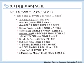
3. 디지털 회로와 VDHL 3.2 조합논리회로 구성요소와 VHDL 조합논리회로 블록(RTL 설계에서 사용되는) • 동기신호가 없는 논리 회로 블록 • NOT, AND, NAND 등의 기본 Gate • Gate들의 연결 형태로 특성이 표현된 회로도 • Boolean Equation으로 동작 특성이 표현된 회로 • Truth Table을 이용하여 동작 특성이 표현된 회로 • Function Table을 이용하여 동작 특성이 표현된 회로 • 1-단 MUX 및 다단 MUX기능을 갖는 회로 • Decoder 및 Encoder의 기능을 갖는 회로 • Shift 또는 Rotate기능을 갖는 회로 • 다양한 연산 알고리즘에 따른 Adder회로 • 여러 가지 기능을 갖도록 정의된 ALU회로 • 3-State Buffer를 요구하는 회로 • 2-Dimensional Memory를 갖는 ROM과 RAM회로
Cont’d • 동기신호가 필요한 논리 회로 블록 • latch • Flip-Flop • Register • Asynchronous Counter • Synchronous Counter • FSM (Finite State Machine)
VHDL의 Test Bench Modeling의 개념 • Test Harness를 위한 기본 구조 • Hardware Model Under Test • Vector Generation (Stimulus and Reference) • Test Harness 내부에서 생성 • Array에 상수 형태로 저장된 Vector를 읽으면서 수행 • 별도의 System File에 저장된 Vector를 읽으면서 수행 • Comparing Actual and Expected Results • assert 구문의 사용
Test Vector Generation의 3가지 방법 • Case2 (clock 및 반복적인 신호 생성) • Case1 (연속적인 stimulus 기술)
Cont’d • Case3 (process 문 사용)
테스트 벤치 구성의 예 • 테스트벤치 코드
Cont’d • 시뮬레이션 예
디지털 시스템에 대한 modeling template • Visibility 부여를 위한 구문 library Pre-compiled_library_name ; use Pre-compiled_library_name. Package_name.ALL ; usework.Package_name.ALL ; • 동기 신호가 없는 회로의 Process 구문 (조합회로) [LABEL :] process(입력 신호를 표시하는 signal 모두를 list 형태로 표현) .. sequential문 사이에 data를 전달하는 variable을 위한 선언문 .. begin .. if, case, for..loop, exit, next문과 같이 논리 합성이 가능한 sequential문을 사용한 표현 .. end process [LABEL] ; • 기본 Modeling Template • library IEEE; use IEEE.std_logic_1164.all; • visibility declaration statements; • entitymodel_nameis • generic (list of generic inputs ) ; • port (list of inputs and outputs ); • endmodel_name ; • architecturearchitecture_nameofmodel_nameis • internal signal declarations; • begin • label : process (sensitivity signal list) • internal variable declarations; • begin • sequential statements; • end process label ; • concurrent behavioral statements; • concurrent procedure call statements; • ... • endarchitecture_name ;
3.2.1 NOT, AND, NAND등 기본 게이트에 대한 표현 • NAND • Entity • Architecture body • architecture RTL2 of NAND2 is • begin • C <= ‘0’ when A=‘1’ and B=‘1’ • else ‘1’; • end RTL2; • architecture RTL1 of NAND2 is • begin • C <= A nand B; • end RTL1; • 그림 3-5(b) signal 할당문 및 conditional signal 할당문에 의한 architecture unit 표현
Cont’d • Selected signal 할당 문 사용
Cont’d • 테스트 벤치 구성
Cont’d • 시뮬레이션 파형
1-Bit Full Adder에 대한 논리 회로도 Modeling Guide Logic Operator와 Basic Signal Assign 구문을 사용하여 각 Gate를 표현. 각 Gate 사이를 연결함에 요구되는 Wire에 대한 기억 장소를 Signal로 선언. 2개 이상의 연속적 Gate를 하나의 Assign 구문으로 표현함도 가능함. 3.2.2 게이트 수준 논리회로등에 대한 표현 • VHDL Modeling • library IEEE; • use IEEE.std_logic_1164.ALL; • entity ADDER is • port (A, B, CIN : in std_logic; • SUM, COUT : out std_logic); • end ADDER; • architecture RTL1 of ADDER is • signal S0, S1, S2 : std_logic; • begin • S0 <= A xor B; S1 <= A and B; • SUM <= S0 xor CIN; • S2 <= S0 and CIN; • COUT <= S1 or S2; • end RTL1; • 논리 합성을 행하는 경우의 예측? • 사용되는 Technology Library가 다르므로 형태가 동일한 회로는 보장 할 수 없음. • 회로도의 기능은 항상 유지됨.
1-Bit 전가산기에 대한 Equation 표현 Architecture Unit에 대한 표현 Data Flow Modeling 방법의 이용 architecture RTL2 of ADDER is begin SUM <= (not A and not B and Cin) or (not A and B and not Cin) or (A and B and not Cin) or (A and B and Cin); COUT <= (not A and B and Cin) or (A and not B and Cin) or (A and B and not Cin) or (A and B and C); end RTL2; 3.2.3 Boolean Equation에 대한 표현 • 임의 Equation에 대한 Entity Unit • entity MULTIBIT is • port (A,B,C : IN • std_logic_vector(3 DOWNTO 0); • Z : OUT std_logic_vector(3 DOWNTO 0)); • end MULTIBIT; • Architecture Unit에 대한 표현(1) • architecture RTL1 of MULTIBIT is • begin • --Multi-bits equation을 하나로 표현 • Z <= A or (B nand C); • end RTL1; • Architecture Unit에 대한 표현(2) • architecture RTL2 of MULTBIT is • begin • --각 bit를 나누어 equation으로 표현 • Z(3) <= A(3) nor (B(3) nand C(3)); • Z(2) <= A(2) nor (B(2) nand C(2)); • Z(1) <= A(1) nor (B(1) nand C(1)); • Z(0) <= A(0) nor (B(0) nand C(0)); • end RTL2;
1-Bit Full-Adder에 대한 Truth Table Modeling Guide 입력 변수들을 & Operator로 Combine하여 새로운 Variable에 기억함. Case 구문을 사용하여 각 Variable의 값을 각 경우로 분류함. 각 경우에 따라 출력 변수를 결정함. Signal Assign 구문을 사용함 Variable Assign 구문의 사용과 최종적인 출력 값 결정 방법 3.2.4 Truth Table에 대한 표현 • Architecture Unit에 대한 표현 • architecture RTL2 of ADDER is • begin • process (A, B, CIN) • variable TMP : • std_logic_vector(2 downto 0); • begin • TMP := A & B & CIN; • case TMP is • when "000" => • SUM <=‘0’; COUT <='0'; • when "001" | "010" | "100" => • SUM <='1'; COUT <='0'; • when "011" | "101" | "110" => • SUM <='0'; COUT <='1'; • when others => • SUM <='1'; COUT <='1'; • end case; • end process; • end RTL2;
Priority Encoder의 Function Table Modeling Guide 선택적 Signal Assign 구문을 이용함. 입력 조건의 우선 순위를 IF 문으로 표현 선택적 Signal Assign 구문을 이용 출력이 하나인 경우에 표현이 간결 architecture RTL1 of FUNC is begin ENC_OUT <= "00" when D = '0' else "01" when C = '0' else "10" when B = '0' else "11” when A = ‘0’ else "XX"; end RTL1; 3.2.5 Function Table에 대한 표현 • Process와 IF 구문을 이용 • 출력이 여러 개 인 경우에 표현이 간결 • architecture RTL2 of FUNC is • begin • process(A, B, C, D) • begin • if D='0' then • ENC_OUT <= "00"; • elsif C='0' then • ENC_OUT <= "01"; • elsif B='0' then • ENC_OUT <= "10"; • elsif A='0' then • ENC_OUT <= "11"; • else • ENC_OUT <= "XX"; • end if; • end process; • end RTL2;
MUX에 대한 Function Table 선택적 Signal Assign 구문을 이용 architecture RTL1 of MUX41 is signal TMP : std_logic_vector(1 downto 0); begin with SEL select TMP <= l0 when "00", l1 when "01", l2 when "10", l3 when others; with ENABLE select Y <= TMP when '0’, "0000" when others; end RTL1; 3.2.6 1-단 MUX • Process와 Case 구문을 이용 • architecture RTL2 of MUX41 is • begin • process(SEL, ENABLE, l0, l1, l2, l3) • begin • if ENABLE='0' then • case SEL is • when "00" => Y <= l0; • when "01" => Y <= l1; • when "10" => Y <= l2; • when others => Y <= l3; • end case; • else • Y <= "0000"; • end if; • end process; • end RTL2; • 입력이 많은 경우의 MUX에 대한 표현 • 소규모 MUX를 이용한 다단 MUX 회로도의 구성과 표현
3.2.7 다단 MUX에 대한 표현 • 1단 8 x 1 MUX와 다단 8 x 1 MUX 회로도
Cont’d • 다단 MUX에 대한 2가지의 VDHL 표현
Encoders • Truth Table for an 8-3 binary encoder
Cont’d • 8-3 encoder modeled from the truth table
Cont’d • Process, case 문 사용
Cont’d • Selected signal assignment 사용
Cont’d • Process, loop 사용
Cont’d • 합성결과
Priority Encoder • Truth Table(8-3)
Cont’d • Different ways of modeling
Cont’d A_int로 바꾸어야 함.
Cont’d Variable n : integer range 0 to 7;
Priority encoder (process, 7 downto 0, exit) The same result As in process – if version
3.2.8 Decoder에 대한 표현 • Enable 신호가 없는 Decoder • 진리표
Cont’d • VHDL 표현
3-8 Decoder • Truth table
Cont’d • Dirrerent ways of modeling
Cont’d Variable N : integer range 0 to 7; For N in 7 downto 0 loop
Decoder (process – if) – synthesis result 2.Conditional signal assignment 3.Process + case version 4.Selected signal assignment 6. Process + for + 7downto 0, exit the same result
Cont’d(Enable 신호가 있는 Decoder 및 7-segment Decoder) • Selected Signal Assign 구문에 의한 표현 • architecture RTL2 of EDECODER is • signal TMP : • std_logic_vector(2 downto 0); • begin • TMP <= G & DATA; • with TMP select • Y <= "1110" when "000", • "1101" when "001", • "1011" when "010", • "0111" when "011", • "1111" when others; • end RTL2; • 7-Segment Decoder에 대한 표현 • Don’t Care 조건을 이용하여 표현하면 면적을 최소화 할 수 있다. • DEC에 대한 Function Table • Process 구문을 이용한 표현 • process (G,DATA) begin • if G='0' then • case DATA is • when "00" => Y <= "1110"; • when "01" => Y <= "1101"; • when "10" => Y <= "1011"; • when others => Y <= "0111"; • end case; • else • Y <= "1111"; • end if; • end process;
Don’t Care 출력 값을 이용한 표현 architecture RTL1 of BCD is begin process (BCD_DATA) begin case BCD_DATA is when "0000" => Y <= "0000001"; when "0001" => Y <= "1001111"; when "0010" => Y <= "0010010"; when "0011" => Y <= "0000110"; when "0100" => Y <= "1001100"; when "0101" => Y <= "0100100"; when "0110" => Y <= "0100000"; when "0111" => Y <= "0001111"; when "1000" => Y <= "0000000"; when "1001" => Y <= "0001100"; -- Don’t Care 출력에 대한 표현 when others => Y <= "-------"; end case; end process; end RTL1; Cont’d • Don’t Care 를 이용하지 않은 표현 • architecture RTL2 of BCD is • begin • process (BCD_DATA) begin • case BCD_DATA is • when "0000" => Y <= "0000001"; • when "0001" => Y <= "1001111"; • when "0010" => Y <= "0010010"; • when "0011" => Y <= "0000110"; • when "0100" => Y <= "1001100"; • when "0101" => Y <= "0100100"; • when "0110" => Y <= "0100000"; • when "0111" => Y <= "0001111"; • when "1000" => Y <= "0000000"; • when "1001" => Y <= "0001100"; • when others => Y <= ”0000000”; • -- when others => null; • end case; • end process; • end RTL2;
12-15 Forth quarter 8-11 Third quarter 7 6 5 4 Second quarter 0-3 First quarter Four bit Address Decoder • Address Map
Cont’d • Second quarter : subdivided into 4 sections • Use if in a for loop
Address decoder(process, if, case) No latches Are inferred
Cont’d • Case문 사용 To avoid latches!!