Honeywell High-Temperature Membrane for OBIGGS Application
180 likes | 375 Views
Explore the development of high-temperature gas separation hollow fiber membrane for OBIGGS application, offering increased gas permeability at elevated temperatures and reduced cooling needs. Discover Honeywell’s innovative membrane, fiber spinning conditions, test results, and key conclusions.

Honeywell High-Temperature Membrane for OBIGGS Application
E N D
Presentation Transcript
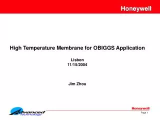
Honeywell High Temperature Membrane for OBIGGS Application Lisbon 11/15/2004 Jim Zhou
Outline • Objectives • Why high temperature membrane? • Fiber spinning conditions • Test results • Conclusions
Objectives • Objectives • To develop a high temperature gas separation hollow fiber membrane suitable for the OBIGGS application • Why high temperature membrane? • Reduce the size and volume of the OBIGG system by taking advantage of higher gas permeability at higher temperatures and reduced cooling requirements at higher OBIGGS operating temperature
Membrane Material Selection Honeywell’s Innovative High Temperature Membrane • High O2, N2 permeability • High O2/N2 Selectivity • Wet spun with very thin selective layer to increase flux • Less susceptible to contaminants • Large operating temperature and pressure range
Membranes and Membrane Modules Nitrogen Oxygen Water Vapor Nitrogen Oxygen and water vapor are “fast” gases which quickly permeate the membrane, allowing nitrogen to flow through the fiber bores as the product stream. Feed Air This illustration shows how fast gases like oxygen and moisture permeate the surface of the individual membrane fibers while nitrogen molecules remain inside and are delivered as the product gas.
Membranes and Membrane Modules End Plate EnrichedNitrogenProductGas Epoxy Tube Sheet Support Core Epoxy TubeSheet Oxygen-Enriched Air Hollow Fibers Feed Air O-Rings Thousands of individual fibers wrapped around a core make up the nitrogen generating hollow fiber membrane module. The engineering of the module is important to maximizing the performance of the whole system.
Fiber Spinning Conditions Phase inversion/Wet spinning process • Pros • Can produce membrane with extremely thin selective layer (Asymmetrical membrane structure) • Cons • Porous support layer may not be stable at high temperatures • Complex spinning and solvent leaching process • Membrane selectivity changes with the amount of solvent left behind
Typical Fiber Spinning Conditions • Fiber spinning condition ranges • Polymer dope rate: 1.2 to 2.5 g/min/per strand • Speed: 75 to 250 ft/min(23 to 76 m/min) • Center solvent rate: 0.5 to 2.0 ml/min • Temperature: Room to 100oC • Fiber ID: 100 to 160 micron • Fiber OD: 150 to 300 micron
Membrane Structure • Thin skin layer with porous support • High gas flux
Conclusions • Membrane is stable at operating temperatures up to 160C • Membrane flux increase with increase temperature • Membrane performance influenced by spinning conditions • High temperature membrane offers advantages over conventional membranes
The Fourth Triennial International Aircraft Fire and Cabin Safety Research Conference The Fourth Triennial International Aircraft Fire and Cabin Safety Research Conference