Download
1 / 28
280 likes | 408 Views
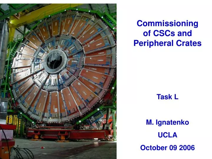
Commissioning of CSCs and Peripheral Crates Task L M. Ignatenko UCLA October 09 2006. Start of CSCs installation. The installation of cathode strip chambers started in June 2003 Installation of the first chamber on an iron disk.

E N D
Commissioning of CSCs and Peripheral Crates Task L M. Ignatenko UCLA October 09 2006
Start of CSCs installation The installation of cathode strip chambers started in June 2003 Installation of the first chamber on an iron disk. The chambers were installed layer by layer and then were cabled.
Installation of the ME+1/3 chamber 36 ME-1/3 CSCs need to be installed
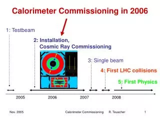
TMB-RAT MPC DCC DDU CCB DMB C C B D M B T M B D M B T M B D M B T M B D M B T M B D M B T M B M P C T M B D M B T M B D M B T M B D M B T M B D M B V M E C O N T R O L L E R DCS Readout Data Track Finder Crate TTC Crate 1 of 5 1 of 5 CFEB CFEB CFEB CFEB CFEB CFEB 1 of 2 1 of 24 ALCT ALCT LVDB LVDB AFEB CSC CSC’s Readout Electronics in USC55 Peripheral Crates (on iron disks) FED Crates (in USC55)
List of CSC Tests 1. Slow Control V/I 3 – Cathode connectivity 2 – Anode connectivity 6 – Comparator noise 5 – SCA noise 4 – AFEB analog noise & threshold 7 – Comparator logic 8 – Chamber noise at nominal HV It takes usually 4-6 hours to test one chamber in perfect conditions It can take a number of days to find a problem, eliminate it and retest the chamber in question
Skew-clear cable revision problem • It was found that we have two type of skew clear cables: Production Revisions A and B - have delay 4.7 ns/meter Production Revisions C and D – have delay 5.2 ns/meter • They differ in terms of data transfer capability:
Chamber noise problem ME+4/1/06-005 ME+2/2/17-039 Noisy channels 360 Hz 590 Hz • Each 15-20th installed chamber needs training either at 3.8 kV or with reverse HV at 3.3-3.4 kV. • Training of chambers with reverse HV polarity helped in most cases. • Two chambers had to be replaced because the training didn’t help
Unexpected cross-talks ME-3/2/08-145 Test pulse was sent to the test strip of the plane #3 ME+3/2/18-075 Test pulse was sent to the test strip of the plane #4
AFEB problems Slice test CSC Test pulse was sent to the test strip of plane #2 • 2 AFEB were replaced (one needs threshold < 0, second one had large crosstalk • ME-1/2/16 – two wire groups in the plane #6 have a short • ME-2/1/09 – one AFEB shows unstable behavior (2-9 channels cab be dead)
Three types of CSC electronics noise observed RMS of SCA pedestals RMS of SCA pedestals AFEB threshold noise So far seen in planes 1, 3, 5 Mostly seen in planes 1, 2, 6 Mostly seen in planes 3, 4, 5
Possible source of CFEB noise Our LV power supplies can be a source of the CFEB noise. LV cable jackets connected to a crate with LV power supplies causes CFEB noise in some chambers. • There are 3 types of chambers: • Good • Acceptable • Noisy
CFEB noise of ME+2/2/28 MTCC, DQM results for Global run 2599 CSC commissioning set-up, Sep 08 Our set-up sees less CFEB noise level
Summary of replacements • 5 boards had mechanical damages: • LVDB – broken input connector • LVMB – broken switch • ALCT – broken input connector • CFEB – broken latch, input connectors • 20 CFEBs were replaced: • 14 CFEBs – dead channels, low response to the test pulse, no comparators, no data, … • 6 CFEBs - by mistakes • 5 LVMB – read wrong currents • 5 ALCT: • four boards had 1.8 V fuse burnt out • one board couldn’t been readout • 9 cables: • one DMB-LVDB was damaged • eight skew clear cables • 4 CSCs: • two chambers couldn’t hold HV > 2.7 kV • two chambers had unacceptable level of noise
Summary table of known problems - Must be repaired - Can be ignored - Can be fix, but needs board replacement or taking a chamber down
C C B D M B T M B D M B T M B D M B T M B D M B T M B D M B T M B M P C T M B D M B T M B D M B T M B D M B T M B D M B C O N T R O L L E R Boards in Peripheral Crate (PC) Data acquisition Motherboard (DMB) Trigger Motherboard (TMB) and RPC-ALCT Transition module (RAT) VME Crate Controller (VCC) Muon Port Card (MPC) Clock & Control Board (CCB) 60 Peripheral Crates for CSC’s in Total.
Lists of new boards and tests • Timing of ALCT Rx and Tx • Timing of CFEB Rx • Wire scan • Strip comparator scan • TMB test • DMB test • TMB-MPC test • TMB-RAT self test • FAST site tests (calibration) • Crate Controller - 1 • CCB - 1 • MPC - 1 • DMB - 9 • TMB - 9 • RAT - 9 • PCRB -1 • MPCB - 1 • Back plane - 1
Peripheral crate commissioning report • There was not comparator data from CFEB #2 of ME+1/2/35 chamber. • The low voltage control cable on ME+1/2/36 chambers didn’t work. • The ALCT fuse on 1.8 V power line of ME-4/1/11 burnt out. • Two CFEB-DMB skew-clear cables were swept.
PC commissioning summary • 62 PC have been assembled and tested in ISR before shipping to SX5 for final installation • 38 PC have been installed filled up with electronics and cabled • 24 PC passed through the first stage of the commissioning • The first stage of installed PC commissioning on minus side has started (3 PC have been commissioned).
Test-B Database User Interfacehttp://cmsdoc.cern.ch/CSC/TESTB/ Instructions Summary Table Traveller AFEB Thresholds
Our plans for 2006-2007 • Commissioning of 36 ME-1/3 chambers which are going to be installed in November-December 2006. • Fix the problems on as many CSCs as possible before they go down the shaft. • Installed most of the Peripheral Crates, fill them up with electronics, and hook up skew clear cables. • Finish first stage of Peripheral Crate commissioning before disks are moved down the shaft. • Redesign set-up for PC commissioning (add FED crate and TTCVi crate. • Develop the software for CSC calibration using PC control and readout. • Develop a database for storage the results of the tests. • Commissioning new set-up for PC and on-chamber electronics test.
Plans on 2006-2007 • PC commissioning and integration with CSCs. • PC and CSC integration with XDAQ. • PC and CSCs integration with cross-DAQ (DQM).
M&O of CSC system 2008-2009 • Full calibration of CSC and CSC’s electronics. • Using particles coming from interaction point make calibration of: • HV sectors (18 for small CSC and 30 for big ones) • Time adjustment of ALCT delays for precision BX • Trigger time adjustment of CSC in PCs • ALCT-CLCT trigger time decision for the chambers in PCs • M&O of the system: • Control and monitoring CSC performance • CSC repair • Failed board replacement • Participation in data taking runs – shifts on duty