Download
1 / 30
300 likes | 720 Views
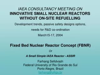
IAEA CONSULTANCY MEETING ON INNOVATIVE SMALL NUCLEAR REACTORS WITHOUT ON-SITE REFUELLING Development trends, passive safety designs options, needs for R&D co-ordination March15-17, 2004 Fixed Bed Nuclear Reactor Concept (FBNR) Or A Small Simple IAEA Reactor - ASSIR

E N D
IAEA CONSULTANCY MEETING ONINNOVATIVE SMALL NUCLEAR REACTORS WITHOUT ON-SITE REFUELLING Development trends, passive safety designs options, needs for R&D co-ordination March15-17, 2004 Fixed Bed Nuclear Reactor Concept (FBNR) Or A Small Simple IAEA Reactor - ASSIR Farhang SefidvashFederal University of Rio Grande do SulPorto Alegre, Brazilfarhang@ufrgs.br
Schematic diagram of the fixed/fluidized bed nuclear reactor concept. (1) structural support; (2) hydraulic valve opener; (3) fuel discharge valve; (4) graphite jacket; (5) reactor core; (6) level limiter shaft; (7) depressurizer; (8) steam exit; (9) level limiter drive; (10) fuel feed; (11) pressurizer; (12) water entrance; (13) steam generator; (14) level limiter; (15) absorber shell; (16) hexagonal channel; (17) fluidization tube; (18) circular channel; (19) fuel chamber; (20) distributor (21) entrance perfurations; (22) coolant entrance; (23) coolant exit; (24) primary pump; (25) reflector; (26) biological shield, (27).fixed bed core, (28) fluidized bed core, (29) spent fuel pool.
Some of the Characteristics of the Proposed Reactor • The Fixed Bed Nuclear Reactor (FBNR) is based on the pressurized light water reactor (PWR) technology. • FBNR is simple in design. • FBNR is a small reactor. • FBNR is a modular reactor. • FBNR is an inherently safe reactor. • FBNR is a passively cooled reactor. • FBNR is an integrated primary circuit reactor. • The reactor core is suspended by the flow of water coolant. The stop in flow causes the fuel elements to leave the reactor core by the force of gravity. • FBNR in its advanced version can use supercritical steam or helium gas as coolant, and may utilize MOX or thorium fuel. It may also be a fluidized bed nuclear reactor.
Fuel Options • Two options are proposed: • 1. A 8 mm diameter spherical fuel element made of uranium dioxide with the density of 10.5 g/cm3, cladded by zircaloy and cooled by pressurized water. • 2. A 8 mm diameter spherical fuel element made of compacted Micro-Fuel-Elements (MFE) with the density of 5.9 g/cm3, cladded by silicon carbide and cooled by pressurized water. • MFE are coated particles and are similar to TRISO fuel with outer diameters about 2 mm. They consist of 1.5 - 1.64 mm diameter uranium dioxide spheres coated with 3 layers. The inner layer is of 0.09 mm thick porous pyrolytic carbide (PYC) with density of 1 g/cm3 called a buffer layer, providing space for gaseous fission products. The second layer is of 0.02 mm thick dense PYC (density of 1.8 g/cm3) and the outer layer is 0.07 - 0.1 mm thick corrosion resistant silicon carbide (SiC). Ceramic protection films, manufactured by chemical vapor deposition (CVD) method, create resistance of graphite components against water and steam at high temperatures (450°- 550° C at normal operating conditions and up to 1400° C at accidental conditions ). Small fuel elements are able to confine fission products indefinitely at a temperature less than 1400° C.
Core Level Limiter Core core Fuel Chamber (high neutron absorber tube) Very Small Reactor Option Fig. 1: Pressurized water flows upward through the 10 cm diameter fuel chamber made of highly neutron absorbing alloy. Then it passes through the 25 cm diameter core of the module. After absorbing heat from the core, it passes through the sieve and an integrated heat exchanger of shell and tube type. Thereafter, it returns down through the outer space between the tubes back to the pump and distributor. For detailed description see www.rcgg.ufrgs./fbnr .
Fig.2: Reactor in operating condition. The 8 mm diameter spherical fuel elements are out of the fuel chamber and are in the core. The core is in critical condition. The reserve reactivity contains in the extra fuel elements that are left in the fuel chamber. A fine control rod may be introduced at the centre of the module should it be necessary.
Fig.3: During shut down or accident conditions. The pump is turned off automatically, so the fuel elements fall back into the fuel chamber through the force of gravity.
Fig.4: Shut down condition. The core is empty and the fuel elements are stored in the fuel chamber in a highly sub critical condition. The decay heat is dissipated through natural convection.
Core Level Limiter Fuel Chamber (high nêutron absorber tube) Small Reactor Option Fig.5: This option reduces the coolant pressure loss in the fixed bed. The pressurized water flows upward through the 10 cm diameter fuel chamber made of highly neutron absorbing alloy. Then it enters the 25 cm diameter core of the module. It flows up into the perforated central tube and thereafter flows horizontally through the fuel elements. After absorbing heat from the core, flows upward passing through an integrated heat exchanger of shell and tube type. Thereafter, it returns down the outer space between the tubes back to the pump and distributor. For detailed description see www.rcgg.ufrgs./fbnr .
Fig.6: Reactor in operating condition. The 8 mm diameter spherical fuel elements are out of the fuel chamber and are in the core. The core is in critical condition. The reserve reactivity contains in the extra fuel elements that are left in the fuel chamber. A fine control rod may be introduced at the centre of the module should it be necessary.
Fig.7: During shut down or accident conditions. The pump is turned off automatically, so the fuel elements fall back into the fuel chamber through the force of gravity.
Fig.8: Shut down condition. The core is empty and the fuel elements are stored in the fuel chamber in a highly sub critical condition. The decay heat is dissipated through natural convection.
Fig.9: The pressure that holds the fixed bed together as a function of coolant velocity.
Fig.10: As the fuel elements leave the reactor and the core height decreases, the reactivity decreases due to the effect of neutron leakage. Here are variations for the reactor diameters of 50 and 150 Cm.
Fig. 11: The reactor power produced as a function of chosen coolant velocity for a 150 Cm diameter reactor. A coolant temperature rise of 40 C is assumed.
Fig.12: Pump power fraction needed to pump coolant through a 1 m height bed as function of coolant velocity.
Fig.13: Pump power fraction needed to pump coolant through a 0,1 m height bed as function of coolant velocity.
Inherent Safety & Passive Cooling • The reactor core is suspended by the flow of water coolant. The stop in flow causes the fuel elements to leave the reactor core by the force of gravity and enter the fuel chamber. • The fuel chamber is a highly subcritical assembly cooled by natural convection. • Detection of any signal due to any type of accident cuts the power from coolant pump.
Waste & Environmental Impact Its spent fuel is in such a convenient form and size that may be utilized directly as the source for irradiation and applications in agriculture and industry. This feature results in a positive impact on waste management and environmental protection.
Scope of a Co-ordinated Research Project (CRP)for the constuction of thePROTOTYPE of the REACTOR • Preparation of the conceptual design of the chosen option or options. • Constuction of a full size non-nuclear hydraulic module to verify the hydraulics behavior and determine the basic parameters. • Realization of neutronics, thermal hydraulics, and structural calculations. • Fabrication and testing of the fuel necessary for the nuclear experiment. • Engineering design of the prototype of the reactor. • Performance of a zero power experiment with one module in a nuclear experimental facility. • Construction of the single module prototype.
WORK PLAN FOR A COORDINATED RESEARCH PROJECT CALCULATIONS • Neutronics calculations (utilizing existing PWR codes chosing spherical fuel option for cross section calculations). • Thermal Hydraulics calculations (utilizig modified PWR codes which may need some verifications). • Structural calculations.
WORK PLAN FOR A COORDINATED RESEARCH PROJECT • NON-NUCLEAR EXPERIMENT: • Construct a full size hydraulic module to observe the behavior of the dummy fuel elements in the reactor: • Obtain a 25 and a 10 cm diameter transparent tubes made from glass or plexiglas. • Obtain 8 mm steel balls commonly used in "ball-bearing" fabrication. • Obtain a 23 and a 3 cm diameter perfurated transparent tubes. • Provide a flowmeter, a pressure gage, and a control valve. • Measure the pressure loss as a fuction of flow rate and observe the bahavior of the spheres in the fixed bed by video-taping the process.
WORK PLAN FOR A COORDINATED RESEARCH PROJECT • NUCLEAR EXPERIMENTS: • FUEL FABRICATION • Obtain UO2 pellets used in conventional PWR. • Grind the cylindrical pellets to form 8 mm diameter spherical pellets. • Stamp out hemispherical shells from a zircaloy sheet. • Press two hemispherical shells against each other with a pellet between them. Then pass an electric current to weld them together in an atmosphere of helium at high pressure. • Check the helium leakage from the fuel element by a He-detector to perform quality control.
WORK PLAN FOR A COORDINATED RESEARCH PROJECT • NUCLEAR EXPERIMENTS: • MODULE FABRICATION • Obtain a 25 cm diameter zircaloy tube. • Obtain a 10 cm diameter stainless steel tube cladded by highly neutron absorbing materials. • Obtain a 23 and 3 cm diameter perfurated zircaloy tubes. • Rent a research facility such as LR-0 facility of UJV in Slovania to perfom full nuclear experiments at zero power using one reactor module.
WORK PLAN FOR A COORDINATED RESEARCH PROJECT ENABLING TECHNOLOGY • Conformation of the existing grinding techniques to transform cylindrical UO2 pellets to spherical pellets. • Conformation of the existing welding technology to clad the spherical fuel elements. • Conformation of the existing helium detecting devices to this particular case. • Adequation of existing technology to control the flow in a pump by frequency control, for reactor purposes.
SOME OF THE POSSIBLE CO-OPERATING INSTITUTIONS • Imperial College of University of London, England. • University of Calgary, Canada. • University of Pisa, Italy. • Delft university, the Netherlands. • Pacific Northwest National Laboratory, USA. • Prof. Seifritz, Switzerland. • UJV – Nuclear Research Centre of Slovania • COPPE, University of Rio de Janeiro, Brazil. • CDTN & IPEN of CNEN, Brazil • ITEP – Russia • Others
Government Research Centres EC Industry Country Ci Private Investors CRP- IAEA Coordinated Research Project, the embryo of WONEC – World Nuclear Energy Company IAEA FINANCIAL SCHEME The cost of the research and development of a simple one module prototype of the reactor to demonstrate its feasibility, may be estimated at $1000 000. If at least 3 European countries take part in the project, the European Community will contribute with 50% of the cost. Thus what is required is that 5 countries participate with $100 000 each.
Raising Funds • Some governments such as Italy contribute with 60% of the cost of energy projects that are considered to be “clean”. Thus $1.00 investment from indusrry attracts $1.50 from the goverment. • If 5 (or 10) countries participate: $1.00 investment raises $25 (or $50.00) for the project. • Therefore, $1.00 investment from indudtry, research centres, or private investors raises $25.00 ( if 5 countries) or $50.00 (if 10 countries) for the project. • The investments can be in the form of service, equipment, or money.
Suggestion for the approval of the Consultancy Meeting • It is recommended that the IAEA nominates a group to draw up a draft proposal for the constitution of an entity that may be called the World Nuclear Energy Company (WONEC) to operate under the auspices of the IAEA. • WONEC is to be responsible for Research and Development and finally construction of the innovative nuclear reactors by drawing on national and international financial resources worldwide. • WONEC will provide nuclear energy to all the interested nations without suffering from adverse effects of nuclear proliferation.