Download

1 / 37
440 likes | 774 Views
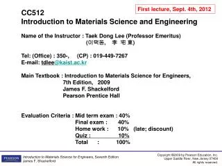
CENG151 Introduction to Materials Science and Selection. Tutorial 2 21 st September, 2007. Teaching Assistants. Candy Lin Rm 7250 Email: kecandy@ust.hk Topics: Crystallography, Phase Diagrams Bryan Wei Rm 7111 Email: kebw@ust.hk

E N D
CENG151 Introduction to Materials Science and Selection Tutorial 2 21st September, 2007
Teaching Assistants • Candy Lin • Rm 7250 • Email: kecandy@ust.hk • Topics: Crystallography, Phase Diagrams • Bryan Wei • Rm 7111 • Email: kebw@ust.hk • Topics: Diffusion, Mechanical Properties, Polymers
Associated with polymers Ceramic combination with a metal © 2003 Brooks/Cole Publishing / Thomson Learning™ © 2003 Brooks/Cole Publishing / Thomson Learning™ Semiconductor materials Metals
© 2003 Brooks/Cole Publishing / Thomson Learning™ Representative strengths of various categories of materials
Atomic Bonding • Primary bonding: Metallic bond, Covalent bond, Ionic bond. • Secondary bonding: Van der Waals interactions (London forces, Debye interaction, Keesom interaction) • Intermetallic compound is a compound such as Al3V formed by two or more metallic atoms
© 2003 Brooks/Cole Publishing / Thomson Learning™ Metallic Bonding • The metallic bond forms when atoms give up their valence electron, then forms an electron sea. • The positively charged atom cores are bonded by mutual attraction to the negatively charged electrons. • When voltage is applied, the sea of electrons can move freely to produce a current.
© 2003 Brooks/Cole Publishing / Thomson Learning™ Covalent Bonding • Covalent bonding requires that electrons be shared between atoms in such a way that each atom has its outer sp orbital filled. • In silicon, with a valence of four, four covalent bonds must be formed.
© 2003 Brooks/Cole Publishing / Thomson Learning™ Ionic Bonding • An ionic bond is the result of electron transfer from one atom to another. • When sodium donates its valence electron to chlorine, each becomes an ion; attraction occurs, and the ionic bond is formed. • It is important to knot that ionic bonds are nondirectional. A positively charged Na+ will attract any adjacent Cl- equally in all directions!
© 2003 Brooks/Cole Publishing / Thomson Learning™ Ionic Bonding • When voltage is applied to an ionic material, entire ions must move to cause a current to flow. Ion movement is slow and the electrical conductivity is poor.
(c) 2003 Brooks/Cole Publishing / Thomson Learning™ Atomic Arrangement • Levels of atomic arrangements in materials: • (a) Inert monoatomic gases have no regular ordering of atoms • (b, c) Some materials, including water vapor, nitrogen gas, amorphous silicon and silicate glass have short-range order. • (d) Metals, alloys, many ceramics and some polymers have regular ordering of atoms/ions that extends through the material.
Example: LCD • Liquid crystal display. • These materials are amorphous in one state and undergo localized crystallization in response to an external electrical field • Widely used in liquid crystal displays. (Courtesy of Nick Koudis/PhotoDisc/GettyImages.)
Lattice, Unit Cells, and Crystal Structures • Lattice - A collection of points that divide space into smaller equally sized segments. • Unit cell – The simplest repeating unit of any structure that can be stacked to fill space. All atoms must be the same in every unit cell. • Atomic radius - The apparent radius of an atom, typically calculated from the dimensions of the unit cell, using close-packed directions (depends upon coordination number). • Packing factor - The fraction of space in a unit cell occupied by atoms.
(c) 2003 Brooks/Cole Publishing / Thomson Learning™ Definition of the lattice parameters • Their use in cubic, orthorhombic, and hexagonal crystal systems
(c) 2003 Brooks/Cole Publishing / Thomson Learning™ Hexagonal close packed structure (HCP) • The hexagonal close-packed (HCP) structure (left) and its unit cell. A B A
For directions: Determine coordinates for “head” and “tail” of the direction “head”-”tail” Clear fraction/reduce results to lowest integers. Enclose numbers in [] and a bar over negative integers. For planes: Identify points at which the plane intercepts the x, y, z axis. Take reciprocals of these intercepts. Clear fractions and do NOT reduce to the lowest integers. Enclose the numbers in parentheses () and a bar over negative integers. Remember Miller Indices?
Special note for directions… • For Miller Indices of directions: • Since directions are vectors, a direction and its negative are not identical! • [100] ≠ [100] Same line, opposite directions! • A direction and its multiple are identical! • [100] is the same direction as [200] ( need to reduce!) • [111] is the same direction as [222], [333]! • Certain groups of directions are equivalent; they have their particular indices because of the way we construct the coordinates. • Family of directions: <111>=[111], [111],[111],[111],…
Special note for planes… • For Miller Indices of planes: • Planes and their negatives are identical (not the case for directions!) • E.g. (020) = (020) • Planes and their multiples are not identical (Again, different from directions!) We can show this by defining planar densities and planar packing fractions. • E.g. (010) ≠ (020) See example! • Each unit cell, equivalent planes have their particular indices because of the orientation of the coordinates. • Family of planes: {110} = (110),(110),(110),(101), (101),… • In cubic systems, a direction that has the same indices as a plane is perpendicular to that plane.
(c) 2003 Brooks/Cole Publishing / Thomson Learning™ Example: Calculating the Planar Density and Packing Fraction Calculate the planar density and planar packing fraction for the (010) and (020) planes in simple cubic polonium, which has a lattice parameter of 0.334 nm. a0 a0
(a0)2 SOLUTION The total atoms on each face is one. The planar density is: The planar packing fraction is given by: However, no atoms are centered on the (020) planes. Therefore, the planar density and the planar packing fraction are both zero. The (010) and (020) planes are not equivalent!
In-Class Exercise 1: Determine planar density and packing fraction. Determine the planar density and packing fraction for FCC nickel in the (100), (110), and (111) planes. Which, if any, of these planes is close-packed? Remember when visualizing the plane, only count the atoms that the plane passes through the center of the atom. If the plane does NOT pass through the center of that atom, we do not count it!
a0 Solution for plane (100) First, find atomic radius for Nickel from Appendix 2, page 797 of Textbook (6th Ed. Shackleford) to calculate the lattice parameter: For (100):
Solution for plane (110) For (110): It is important to visualize how the plane is cutting across the unit cell – as shown in the diagram! a0
Solution for plane (111) For (111): Again try to visualize the plane, count the number of atoms in the plane: Therefore, plane (111) is close-packed!
In-Class Exercise 2: Determine planar density and packing fraction. Determine the planar density and packing fraction for BCC lithium in the (100), (110), and the (111) planes. Which, if any, of these planes is close packed?
Solution for plane (100) First, find atomic radius for Nickel from Appendix 2, page 797 of Textbook (6th Ed. Shackleford) to calculate the lattice parameter: For (100):
Solution for plane (110) For (110): It is important to visualize how the plane is cutting across the unit cell – as shown in the diagram!
Solution for plane (111) For (111): Note: Since the (111) does NOT pass through the center of the atom in the middle of the BCC unit cell, we do not count it! There are only (3)(1/6)=1/2 atoms in the plane. Therefore, there is no close-pack plane in BCC!
X-Ray Diffraction (XRD) • Max von Laue (1879-1960) won the Nobel Prize in 1912 for his discovery related to the diffraction of x-rays by a crystal. • William Henry Bragg (1862-1942) and his son William Lawrence Bragg (1890-1971) won the 1915 Nobel Prize for their contributions to XRD. • Diffraction – The constructive interference, or reinforcement, of a beam of x-rays or electrons interacting with a material. The diffracted beam provides useful information concerning the structure of the material. • Used widely as an equipment to determine crystal structures of various materials.
(c) 2003 Brooks/Cole Publishing / Thomson Learning • Destructive (out of phase) x-ray beam gives a weak signal. • Reinforcing (in phase) interactions between x-rays and the crystalline material. Reinforcement occurs at angles that satisfy Bragg’s law.
Bragg’s Law: Bragg’s Law: • Where is half the angle between the diffracted beam and the original beam direction • is the wavelength of X-ray d is the interplanar spacing Interplanar spacing: d Miller Indices
Interplanar spacing (d-spacing) • The distance between two adjacent parallel planes of atoms with the same Miller Indices (dhkl). • The interplanar spacing in cubic materials is given by the general equation: • where a0 is the lattice parameter and h,k and l represent the Miller Indices of the adjacent planes being considered.
(c) 2003 Brooks/Cole Publishing / Thomson Learning (a) Diagram of a diffractometer, showing powder sample, incident and diffracted beams. (b) The diffraction pattern obtained from a sample of gold powder.
Example: Examining X-ray Diffraction The results of a x-ray diffraction experiment using x-rays with λ = 0.7107 Å (a radiation obtained from molybdenum (Mo) target) show that diffracted peaks occur at the following 2θ angles: Determine the crystal structure, the indices of the plane producing each peak, and the lattice parameter of the material.
EXAMPLE SOLUTION We can first determine the sin2 θ value for each peak, then divide through by the lowest denominator, 0.0308.
EXAMPLE SOLUTION (Continued) We could then use 2θ values for any of the peaks to calculate the interplanar spacing and thus the lattice parameter. Picking peak 8: 2θ = 59.42 or θ = 29.71 Å Å This is the lattice parameter for body-centered cubic iron.
Answer: The distance between the 0,0,0 and 1,1,1 point is: The interplanar spacing is: Now, the number of interplanar spacings (d111) between the specified points are: In-Class Exercise 3: Repeat Distance In a FCC unit cell, how many d111 are present between the 0,0,0 point and 1,1,1 point?
End of Tutorial 2 Happy Mid-Autumn Festival!