Download
1 / 13
130 likes | 250 Views
Chap 2. Operational amplifiers (op-amps). Circuit symbol of an op-amp. Widely used Often requires 2 power supplies + V Responds to difference between two signals. 2.2 Ideal op-amp. Characteristics of an ideal op-amp R in = infinity R out = 0

E N D
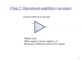
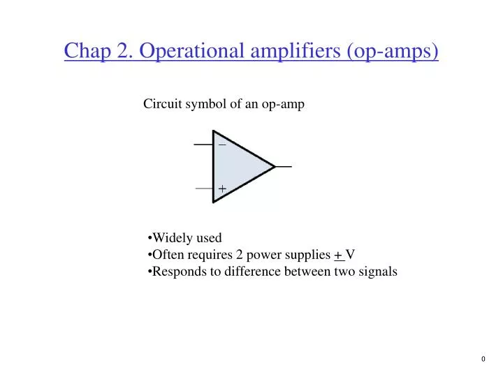
Chap 2. Operational amplifiers (op-amps) Circuit symbol of an op-amp • Widely used • Often requires 2 power supplies + V • Responds to difference between two signals
2.2 Ideal op-amp • Characteristics of an ideal op-amp • Rin = infinity • Rout = 0 • Avo = infinity (Avo is the open-loop gain, sometimes A or Av of the op-amp) • Bandwidth = infinity (amplifies all frequencies equally)
+ - Model of an ideal op-amp I+ V+ + I- Vout = A(V+ - V-) V- - • Usually used with feedback • Open-loop configuration not used much
Summary of op-amp behavior Vout = A(V+ - V-) Vout/A = V+ - V- Let A infinity then, V+ -V- 0
Summary of op-amp behavior V+ = V- I+ = I- = 0 Seems strange, but the input terminals to an op-amp act as a short and open at the same time
To analyze an op-amp circuit • Write node equations at + and - terminals (I+ = I- = 0) • Set V+ = V- • Solve for Vout
2.3 Inverting configuration Very popular circuit
Analysis of inverting configuration I2 I1 = (Vi - V- )/R1 I2 = (V-- Vo)/R2 set I1 = I2, (Vi - V-)/R1 = (V- - Vo)/R2 but V-= V+ = 0 Vi / R1 = -Vo / R2 Solve for Vo Vo / Vi = -R2 / R1 I1 Gain of circuit determined by external components
Rf R1 V1 V2 V3 R2 R3 2.4 Applications of the inverting configuration Current in R1, R2, and R3 add to current in Rf (V1 - V-)/R1 + (V2 - V-)/R2 + (V3 - V-)/R3 = (V- - Vo)/Rf Set V-= V+ = 0, V1/R1 + V2/R2 + V3/R3 = - Vo/Rf solve for Vo, Vo = -Rf(V1/R1 + V2/R2 + V3/R3) This circuit is called a weighted summer
I I Vi 2.5 Noninverting configuration (0 - V-)/R1 = (V- - Vo)/R2 But, Vi = V+= V-, ( - Vi)/R1 = (Vi - Vo)/R2 Solve for Vo, Vo = Vi(1+R2/R1)
Input resistance of noninverting amplifier Rin = Vin / I, from definition Rin = Vin / 0 Rin = infinity V- I Vout = A(V+ -V-) V+
Input resistance of inverting amplifier Rin = Vin / I, from definition I = (Vin - Vout)/R I = [Vin - A (V+ - V-)] / R But V+= 0 I = [Vin - A( -Vin)] / R Rin = VinR / [Vin (1+A)] As A approaches infinity, Rin = 0 I V- V+ Vout = A(V+ - V-)
Vi Summary of op-amp behavior Inverting configuration Noninverting configuration Vi Rin = 0 at this point Vo/Vi = 1+R2/R1 Rin = infinity Vo /Vi = - R2/R1 Rin = R1