NFC Sensor System Integration for Real-Time Remote Monitoring
The project involves connecting sensors to MCU and NFC, enabling real-time data transmission and monitoring via Bluetooth and Android devices. The system is powered through NFC and features a smart bandage concept for constant monitoring. Challenges include induction power operation and antenna implementation. Components include TI MSP430FR5969 MCU, RF430CL330H NFC Module, and PN532 NFC Shield.

NFC Sensor System Integration for Real-Time Remote Monitoring
E N D
Presentation Transcript
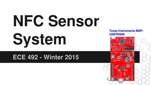
NFC Sensor System Texas Instruments MSP-430FR5969 ECE 492 - Winter 2015
Group Members • Mike Pappas • Sensor connections to MCU and NFC • Nigel Himmelreich • NFC connection to DE0 and Bluetooth • Eric Anderson • Bluetooth-Android communication, data logging and sensor display application
Functionality • Inspired by a disposable ‘Smart Bandage’ • Transmits real time sensor data over NFC • Inductively powered via NFC • Transfers NFC data to Bluetooth for constant monitoring via DE0 • Data logging/display on Android
Design - Sensor Connections As of Feb 8, 2015
Design - Software • MCU • Gather sensor data • Package into NDEF (NFC data format) and send • DE0 • Read from NFC and log • Send data over Bluetooth • Smartphone • Read current sensor data • Display current and past data graphically
Design - Sensor Software Flow Diagram • Induction power does not allow for idling • Power on -> Initialize -> Perform Read -> Power Off (lose power)
Design - Challenges • Induction power - difficult to operate on 100μA. • Challenging antenna implementation (≃1mm x 1.8mm Schottky diodes with < 0.4V forward voltage) • NFC to DE0 communication - minimal resources available
Design - Calculations Antenna Design where • a = (ri + ro)/2 • b = ro – ri • ri = Inner radius of the spiral • ro = Outer radius of the spiral • N = number of turns
Design - Components • Thermal sensor and light diode • TI MSP430FR5969 MCU • TI RF430CL330H NFC Module • PN532 NFC Shield • DE0 Nano • MOD-BT Bluetooth Module • Android Device
/* From RF430.h */ //MSP-EXP430FR5969 port definitions //I2C #definePORT_I2C_OUT P1OUT #definePORT_I2C_DIR P1DIR #definePORT_I2C_SEL0 P1SEL0 #define PORT_I2C_SEL1 P1SEL1 #define SDA BIT6 #define SCL BIT7 //INTO #define PORT_INTO_IN P2IN #define PORT_INTO_OUT P2OUT #define PORT_INTO_DIR P2DIR #define PORT_INTO_SEL0 P2SEL0 #define PORT_INTO_SEL1 P2SEL1 #define PORT_INTO_REN P2REN #define PORT_INTO_IE P2IE #define PORT_INTO_IES P2IES #define PORT_INTO_IFG P2IFG #define INTO BIT2 Code Example - RF430 Init. /* From main.c */ // Disable the GPIO power-on default high-impedance mode // to activate previously configured port settings PM5CTL0 &= ~LOCKLPM5; // Configure pins for I2C PORT_I2C_SEL0 &= ~(SCL + SDA); PORT_I2C_SEL1 |= SCL + SDA; //Configure eUSCI for I2C Mode //Set I2C mode, Master mode, sync, transmitter UCB0CTLW0 |= UCMODE_3 + UCMST + UCSYNC + UCTR; UCB0CTLW0 |= UCSSEL_2; // SMCLK = 8MHz //configure pin for INTO interrupts PORT_INTO_SEL0 &= ~INTO; // GPIO PORT_INTO_SEL1 &= ~INTO; // GPIO PORT_INTO_DIR &= ~INTO; // Input PORT_INTO_OUT |= INTO; // Output high for pullup PORT_INTO_REN |= INTO; // Internal pullup resistor PORT_INTO_IFG &= ~INTO; // Clear interrupt flag PORT_INTO_IES |= INTO; // Fire interrupt on high-to-low transition // since INTO is setup active low
Test Plans • Unit Testing • Test sensor data being read to MCU • Test NFC data is being sent from MCU to DE0 • Test Bluetooth data from DE0 to smartphone • Verify logging ability of DE0 and smartphone • Test smartphone app and functionality • Integration Testing • Test overval data from sensors to smartphone • Verify correct data logged
Optional features • Inductively power the NFC, MCU, & sensors via power from the NFC antenna when communicating with the receiving board • Add additional sensors • Join the NFC, MCU, & sensors all on one single circuit board with integrated antenna