Download
1 / 17
190 likes | 398 Views
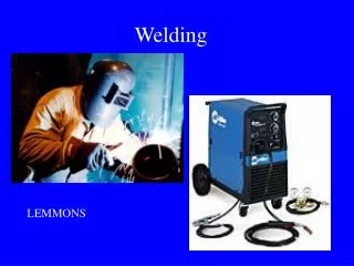
WELDING. Introduction. Late 19 th Century Scientists/engineers apply advances in electricity to heat and/or join metals (Le Chatelier, Joule, etc.) Early 20 th Century Priorly welding was not trusted as a method to join two metals due to crack issues 1930’s and 40’s

E N D
Introduction • Late 19th Century • Scientists/engineers apply advances in electricity to heat and/or join metals (Le Chatelier, Joule, etc.) • Early 20th Century • Priorly welding was not trusted as a method to join two metals due to crack issues • 1930’s and 40’s • Industrial welding gains acceptance and is used extensively in the war effort to build tanks, aircraft, ships, etc. • Modern Welding • the nuclear/space age helps bring welding from an art to a science
Types of Welding Fusion Welding Pressure Welding Friction Welding Homogeneous Heterogeneous Brazing Soldering Gas Welding Electroslag MIG TIG High Energy Beam Shielded Metal Arc – “Stick” Electric Arc
Important Points • Metallurgical Capacity • Parent metal will join with the weld metal without formation of deleterious constituents or alloys • Mechanical Soundness • Joint will be free from discontinuities, gas porosity, shrinkage, slag, or cracks • Serviceability • Weld is able to perform under varying conditions or service (e.g., extreme temperatures, corrosive environments, fatigue, high pressures, etc.)
Fusion Welding • Base metal is melted • Filler metal may be added • Heat is supplied by various means • Oxyacetylene gas • Electric Arc • Plasma Arc • Laser ELECTRODE COATING CORE WIRE WELDING ATMOSPHERE ARC STREAM ARC POOL SOLIDIFIED SLAG PENETRATION DEPTH WELD BASE METAL
Metal Protection • During fusion welding, the molten metal in the weld “puddle” is susceptible to oxidation • Must protect weld puddle (arc pool) from the atmosphere • Methods • Weld Fluxes • Inert Gases • Vacuum
Weld Fluxes • Typical fluxes • SiO2, TiO2, FeO, MgO, Al2O3 • Produces a gaseous shield to prevent contamination • Act as scavengers to reduce oxides • Add alloying elements to the weld • Influence shape of weld bead during solidification
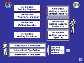
Inert Gases • Argon, helium, nitrogen, and carbon dioxide • Form a protective envelope around the weld area • Used in • MIG • TIG • Shield Metal Arc Vacuum • Produce high-quality welds • Used in electron beam welding • Nuclear/special metal applications • Zr, Hf, Ti • Reduces impurities by a factor of 20 versus other methods • Expensive and time-consuming
Types of Fusion Welding • Oxyacetylene Cutting/Welding • Shielded Metal Arc (“Stick”) • Metal Inert Gas (MIG) • Tungsten Inert Gas (TIG)
Oxyacetylene Welding TORCH TIP 2300 deg F • Flame formed by burning a mix of acetylene (C2H2) and oxygen • Fusion of metal is achieved by passing the inner cone of the flame over the metal • Oxyacetylene can also be used for cutting metals Inner Cone: 5000-6300 deg F Combustion Envelope 3800 deg F Shielded Metal Arc (Stick) • An electric arc is generated between a coated electrode and the parent metal • The coated electrode carries the electric current to form the arc, produces a gas to control the atmosphere and provides filler metal for the weld bead • Electric current may be AC or DC. If the current is DC, the polarity will affect the weld size and application (3)
Inert Gas Welding For materials such as Al or Ti which quickly form oxide layers, a method to place an inert atmosphere around the weld puddle had to be developed Metal Inert Gas (MIG) Uses a consumable electrode (filler wire made of the base metal) Inert gas is typically Argon DRIVE WHEELS CONSUMABLE ELECTRODE POWER SOURCE SHIELDING GAS ARC COLUMN BASE METAL PUDDLE
Tungsten Inert Gas (TIG) Tungsten electrode acts as a cathode A plasma is produced between the tungsten cathode and the base metal which heats the base metal to its melting point Filler metal can be added to the weld pool TUNGSTEN ELECTRODE (CATHODE) POWER SOURCE TUNGSTEN ELECTRODE + + + + - - - SHIELDING GAS ARC COLUMN BASE METAL PUDDLE BASE METAL (ANODE)
Welding Positions INCREASING DIFFICULTY FLAT HORIZONTAL VERTICAL
Weld Defects • Undercuts/Overlaps • Grain Growth • A wide T will exist between base metal and HAZ. Preheating and cooling methods will affect the brittleness of the metal in this region • Blowholes • Are cavities caused by gas entrapment during the solidification of the weld puddle. Prevented by proper weld technique (even temperature and speed)
Weld Defects • Inclusions • Impurities or foreign substances which are forced into the weld puddle during the welding process. Has the same effect as a crack. Prevented by proper technique/cleanliness. • Segregation • Condition where some regions of the metal are enriched with an alloy ingredient and others aren’t. Can be prevented by proper heat treatment and cooling. • Porosity • The formation of tiny pinholes generated by atmospheric contamination. Prevented by keeping a protective shield over the molten weld puddle.
Residual Stresses • Rapid heating and cooling results in thermal stresses detrimental to joint strength. • Prevention • Edge Preparation/Alignment – beveled edges and space between components to allow movement • Control of heat input – skip or intermittent weld technique • Preheating – reduces expansion/contraction forces (alloys) and removes moisture from the surface • Peening – help metal stretch as it cools by hitting with a hammer. Use with care since it may work harden the metal • Heat Treatment – “soak” the metal at a high temperature to relieve stresses • Jigs and Fixtures – prevent distortion by holding metal fixed • Number of Passes – the fewer the better.
Joint Design BUTT JOINT FILLET JOINT STRAP JOINT CORNER JOINT LAP JOINT