Download
1 / 30
320 likes | 454 Views
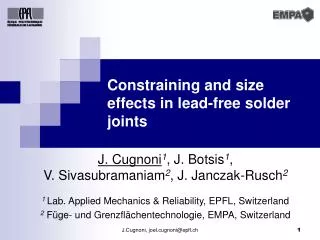
Constraining and size effects in lead-free solder joints. J. Cugnoni 1 , J. Botsis 1 , V. Sivasubramaniam 2 , J. Janczak-Rusch 2 1 Lab. Applied Mechanics & Reliability, EPFL, Switzerland 2 Füge- und Grenzflächentechnologie, EMPA, Switzerland. Nature of Irreversible Deformations. Objectives.

E N D
Constraining and size effects in lead-free solder joints J. Cugnoni1, J. Botsis1, V. Sivasubramaniam2, J. Janczak-Rusch2 1 Lab. Applied Mechanics & Reliability, EPFL, Switzerland 2 Füge- und Grenzflächentechnologie, EMPA, Switzerland J.Cugnoni, joel.cugnoni@epfl.ch
Nature of Irreversible Deformations Objectives Global Project Interface Micro Structure ConstitutiveEquations Thermo-mechanical History Size / ConstrainingEffects Manufacturing Deformation & damage of lead-free solder joints • Plastic constitutive law of Sn-4.0Ag-0.5Cu solder • Variable solder gap width • Effects of constraints • Effects of size ? J.Cugnoni, joel.cugnoni@epfl.ch
Rigid substrates: - impose lateral stresses at the interfaces - additionnal 3D stresses => apparent hardening => constraining effects Plastic deformation of solder: - constant volume - shrinks in lateral directions Solder joint in tension: - stiff elastic substrates - plastic solder (n~=0.5) Constraints in solder joints J.Cugnoni, joel.cugnoni@epfl.ch
w g L t Parametric FE study • Goal: • study the constraining effects as a function of geometry • Method: • parametric FE simulation of 30 joint geometries with the same materials • parameters: • gap to thickness ratio G = g / t • width to thickness ratio W = w / t • indicators: • constraining effect ratio Q = (sujoint - susolder) / susolder • triaxiality ratio R = p / sm J.Cugnoni, joel.cugnoni@epfl.ch
FEM Cu Cu Solder Stress field in constrained solder s11 s22 Front surface view 47 MPa 76 MPa 37 MPa 70 MPa Mid-plane view J.Cugnoni, joel.cugnoni@epfl.ch
FEM Cu Cu Solder Stress field in constrained solder Von Mises eq. stress Hydrostatic pressure Front surface view 54 MPa -47 MPa 58 MPa -37 MPa Mid-plane view J.Cugnoni, joel.cugnoni@epfl.ch
Parametric FE study: Results => Constraining effects are due to the the triaxiality of the stress field in the solder induced by the substrate J.Cugnoni, joel.cugnoni@epfl.ch
Parametric FE study: Results => Constraining effects are inversely proportionnal to the gap to thickness ratio G (asymptotic effect in the form of 1/G) J.Cugnoni, joel.cugnoni@epfl.ch
Parametric FE study: Results • Constraining effects are: • strongly dependent on the gap to thickness ratio G for G<0.5 • slightly affected by the width to thickness ratio W for W<2. J.Cugnoni, joel.cugnoni@epfl.ch
Apparent stress - strain curve of the solder in a joint Constitutive law of the solder is needed for FE simulations is what we usually measure independent of geometry depends on geometry Constitutive law & constraints 3D FEM:includes all the geometrical effects ??? Inverse numerical identification of a 3D FEM J.Cugnoni, joel.cugnoni@epfl.ch
In situ characterization method In-situ characterization of constitutive parameters Experimental SpecimenProduction TensileTest (DIC) Experimental Load - Displacement Curve Apparent engineering stress-strain response of the joint Constraining Effects Identification Loop Optimization (Least Square Fitting) Constitutive stress-strain lawof the solder Geometry FEM Simulated Load - Displacement Curve Numerical Simulations J.Cugnoni, joel.cugnoni@epfl.ch
Experimental setup Tensile tests: • Sn-4.0Ag-0.5Cu solder • production: 1-2 min at 234°C (heating rate 3-4°C/min) and rapid cooling in water • 0.25 to 2.4 mm gap width • Displacement ramp 0.5 mm/s Digital Image Correlation: • is used to determine the displacement "boundary condition" near the solder layer • gauge length =~ 1.5 x solder gap • Displacement res. up to 0.1 mm J.Cugnoni, joel.cugnoni@epfl.ch
micro - Digital Image Correlation micro-DIC measurements: • Requirements: • DIC needs medium & high frequency details in each sub images => random pattern • micro-measurements: spacial & displacement resolution limited mainly by the pattern • no change in magnification & no loss of focus => difficult with optical microscopy • Pattern created by: • rough polishing (contrast in reflexion, uniform light field) • spray paint (best results for global measurements) • Inkjet printing (in progress) 2 - 4 mm J.Cugnoni, joel.cugnoni@epfl.ch
Digital Image Correlation algorithm DIC algorithm: • Features: • Custom developed in Matlab & C • Based on linear / cubic sub-pixel interpolation • Displacement and derivatives (optional) • Optimization: • original "brute" search • simplex or gradient based optimizer • hybrid "pyramidal" search & gradient optimizer • hybrid FFT-based DSC & gradient fine search • Performance: • up to 0.02 pixel displacement resolution (ideal pattern) 4 mm J.Cugnoni, joel.cugnoni@epfl.ch
Similar results for G > 0.5 Constrained stress-strain curves Clear hardening for G < 0.5 Constraining & scale effects => can't compare these curves Identify constitutive properties J.Cugnoni, joel.cugnoni@epfl.ch
Imposed displacement from testing Cu Simulated load-displacement curve Sn-Ag-Cu Elongation of solder Finite Element Modelling • 3D FEM of 1/8th of the specimen • Copper: • Elastic behaviour: ECu = 112 GPa, n = 0.3 • Solder: • Elasto-plastic with isotropic exponential & linear hardening • Chosen to fit bulk solder plastic response • 5 unknown parameters: J.Cugnoni, joel.cugnoni@epfl.ch
Load - displacement curves Blue: initial load-displ. curve Red: identified load-displ. curveBlack: measured load-displ. curve Inverse identification procedure • Identification parameters: • Objective function e(a): • difference of measured and simulated load-displacement curves • non-linear least square optimization algorithm to solve: • Solution time: • 50 FE solutions required to identify the material properties (~2h) • Accuracy: • max error +/-4% on load – displacement curve J.Cugnoni, joel.cugnoni@epfl.ch
Identified constitutive parameters Mechanical properties decreasing for smaller joints: combination of scale effects & porosity !! Manufacturing process is also size dependant !! Removed constraining effects => can compare with bulk specimen Bulk specimen appears much softer !! In-situ characterization !! J.Cugnoni, joel.cugnoni@epfl.ch
+ 15 % Constraining effects 2.4 mm J.Cugnoni, joel.cugnoni@epfl.ch
+ 22 % Constraining effects 1.2 mm J.Cugnoni, joel.cugnoni@epfl.ch
+ 30 % Constraining effects 0.7 mm J.Cugnoni, joel.cugnoni@epfl.ch
+ 37 % Constraining effects 0.5 mm J.Cugnoni, joel.cugnoni@epfl.ch
+ 78 % Constraining effects 0.25 mm J.Cugnoni, joel.cugnoni@epfl.ch
decrease of yield & ultimate stress ~10 MPa Size effects constraining effects ~ 35 MPa J.Cugnoni, joel.cugnoni@epfl.ch
2.4mm 0.7mm 0.5mm (vacuum) Microstructure & Fractography Microstructure before testing Fractography • Pores: • created during manufacturing and grows with plastic deformation • introduces large scatter in experimental data => modelling? • interacts with the interfaces => critical defect!! • size of pores ~ constant for all gap but more influence in thinner joints J.Cugnoni, joel.cugnoni@epfl.ch
FE model DIC measurements plastic damage & void growth in center => crack Damage mechanisms Thick Joint G>1 = small triaxiality Fractography J.Cugnoni, joel.cugnoni@epfl.ch
Fractography DIC measurements Damage mechanisms FE model Thin joint G<0.5 = High triaxiality void growth & crack at interface J.Cugnoni, joel.cugnoni@epfl.ch
Conclusions • Constraining effects: • Proportionnal to triaxility of the stress field in the solder • Inversely proportionnal to the gap to thickness ratio G • Can completely modify the solder joint response: • in an ideal case, ultimate stress increased by a factor of 6 compared to the ult. stress of the solder material itself • Must be taken into account in Characterization & Design • In-situ characterization method: • A versatile & powerful technique for characterization of small size & thin layer materials produced with realistic processing and geometry conditions • Can determine actual constitutive properties from constrained materials J.Cugnoni, joel.cugnoni@epfl.ch
Conclusions • Size & scale effects in lead-free solders • Actual constitutive properties are size dependant: • In the present case, ult. stress decreases by 20% from 2.4mm to 0.2mm joints due to effects of porosity. • material scale effects & the "scaling" of the production methods have a combined influence. • Constraining effects: • Constraining effects are size dependant ~(1/G) with G=g/t • Up to 80% of additionnal hardening due to plastic constraints • solder joint response & constitutive properties are NOT equivalent • stress-strain response solder joint curves are geometry dependant => should not be compared for diff. geometries J.Cugnoni, joel.cugnoni@epfl.ch
Realistic Experiment (DIC) Mixed num-expidentification: realistic properties Design / processvalidation FE Analysis & optimization Future developments • In-situ characterization: • Apply to shear tests • Extend to identification of visco-elasto-plasticity with damage • Reduced object size • Industrial aspects: • Apply the in-situ characterization method to an industrial electronic package (for example BGA) • Determination of the mechanical properties of a solder joint under realistic loading conditions (power-cycles) J.Cugnoni, joel.cugnoni@epfl.ch