Download
1 / 19
200 likes | 546 Views
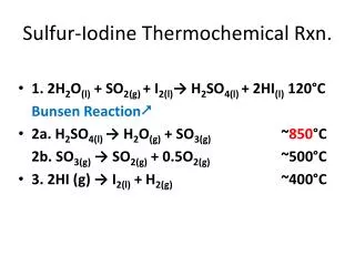
Sulfur-Iodine Thermochemical Rxn . 1. 2H 2 O (l) + SO 2(g ) + I 2(l ) → H 2 SO 4(l ) + 2HI (l ) 120 ° C Bunsen Reaction 2a . H 2 SO 4(l ) → H 2 O (g ) + SO 3(g) ~ 850 °C 2b . SO 3(g) → SO 2(g ) + 0.5O 2(g ) ~500°C

E N D
Sulfur-Iodine ThermochemicalRxn. • 1. 2H2O(l)+ SO2(g) + I2(l)→ H2SO4(l) + 2HI(l)120°C Bunsen Reaction • 2a. H2SO4(l) → H2O(g) + SO3(g) ~850°C 2b. SO3(g)→ SO2(g) + 0.5O2(g) ~500°C • 3. 2HI (g) → I2(l) + H2(g) ~400°C
Reactive Distillation • Equilibrium of reversible reaction highly temperature dependent • A + B C + D • Using L’Chatlier’s Principle: • A + B C + D • Heating mixture and extracting product will push reaction to right
Vacuum Distillation • Each stage considered for the sulfur process (DOE) • Low pressures (compared to the bunsen reactor) allows for high distillation • Note materials consideration http://www.hydrogen.energy.gov/pdfs/review05/pd27_pickard.pdf
Materials • Corrosive environment – H2SO4 , HI, H3PO4 • High temperature • Closed system – three part reaction • Iodine section may generate residual solids
Incoloy 800H: • Nickel-iron-chromium alloy, high strength, resistant to oxidation and carburization, temperatures above 1100°F • Pt, Au, SiC coating • Very unreactive, ceramics and other polymer coatings a consideration • Pt, Cu, Fe2O3 • Catalysts, Cu and Fe2O3 cheap • Hastelloy C-276 (B-2) • Nickel-moly-chromium superalloywith resistance to corrosion and oxidation • Saramet • “Sulphuric acid resistant alloy metal”; due to high Si content – a.k.a. Si steels, with chromium and nickel balance
Against other methods • Steam reforming – CH4 + H2O → CO + 3 H2 CO + H2O → CO2 + H2 Doesn’t cut out carbon emission • High or low temp electrolysis: H2O → O2 + H2 Needs extremely high temperatures for efficiencies ~45% • Others - methanol: CO2 + 3H2→ CH3OH + H20 - dimethyl ether CH3OCH3 - Ammonia NH3
DOE Hydrogen Program • 2002 – 2008 (report in 2005 states 25% progress towards objectives) • Funding – $4.2M • Sandia Labs – H2SO4 reactor • CEA (Commissariat à l'énergieatomique) – Bunsen reactor • General Atomics (Japan) – Iodine Reactor/H2 extractor
Very High Temperature Reactor (VHTR) “To produce hydrogen economically, a reactor must operate at extremely high temperatures. Thus the VHTR has been selected for future hydrogen production plants. ‘The VHTR has the highest priority among the U.S. reactor concepts,’ [Bill] Corwin says, ‘because it fits into the President's plan for the hydrogen economy.’” -”Can the Next Generation Take the Heat?” ORNL Review. http://www.ornl.gov/info/ornlreview/v37_1_04/article_02.shtml. 30 Nov 2010. • Current R&D – DRAGON, Peach Bottom • ONRL – NGNP design: graphite moderated • Metal-cooled fast reactors • Gas-cooled reactors: pebble bed • Numerous other designs, narrowed down by the DOE in the past two years • Deployment anticipated 2025 • Varied fuel types and coatings – if outlet 900°C, fuel needs 1300°C
Boiling Water Reactor (BWR) • Constrained by coolant • Low fuel temperature (compare PWR) • Larger pressure vessel – higher cost • PWRs: ~10% higher performance, increased temperature, but also has a ceiling
Pebble Bed Reactor • Helium coolant: low density – collisions minimized • High flow for low specific heat capacity • Significant lethargy – slow neutrons (though graphite requires more collisions) • 300,000 pebbles, 350 discarded daily Involved fuel handling process
Sodium-Cooled Fast Reactor (SFR) • Closed fuel cycle • Two lines of flow – HX between Pb and H2O • Fertile uranium, plutonium, and other actinides • Operates near ambient pressure • Difficulties with VHTR: Na melting point – 98°C (At ambient pressure) Na boiling point – 883°C • Na highly reactive and corrosive
Lead-Cooled Fast Reactor (LFR) • Lead/Bismuth coolant • Very similar to SFR – closed system liquid metal • Replaceable fuel module, designed to run 15-20 years • Designed to meet the needs of a small grid • Following design features U-Tube HX • Another Gen. IV design replaces liquid metal with helium, maintaining similar design but with varied HX
Advantages • Only liquid and vapor for fluid cycle • Sulfur and iodine components remain in system, H2and O2 distilled out • Chemicals relatively cheap (HBr out of consideration) • Existing R&D – actualization is not too far off • Functional with intermittent renewables or unused heat of gen. IV reactors • No carbon footprint • Ƞ ~ 50%, beats HT electrolysis
Disadvantages • Three components, cumbersome setup Full cycle has not been perfected • Corrosive intermediates (HI, H2SO4, H3PO4) • High materials cost • Much R&D still necessary • Must wait on nuclear technology to advance – subject to public opinion, economy, legislature • Large scale necessary for satisfactory efficiencies (investment)
References • “Boiling Water Reactors”. Nuclear Regulatory Commission. Oct 1 2008. <http://www.nrc.gov/reactors/bwrs.html>. 30 Nov 2010. • “Can The Next Generation Take The Heat?” Oak Ridge National Lab Review. Volume 37, Number 1, 2004. <http://www.ornl.gov/info/ornlreview/v37_1_04/article_02.shtml>. 30 Nov 2010. • Mashue, Timothy; Folger, H. S. “Reactive Distillation”. University of Michigan. 1998. <http://www.engin.umich.edu/~cre/web_mod/distill/>. 10 Nov 2010. • Mathias, Paul M.; Brown, L. C. “Thermodynamics of the Sulfur-Iodine Cycle for Thermochemical Hydrogen Production”. Society of Chemical Engineers, 68th annual meeting. 23 Mar 2003. <http://www.aspentech.com/publication_files/TP51.pdf>. 30 Nov 2010. • “Modular Pebble Bed Reactor”. MIT Department of Nuclear Science and Engineering. <http://web.mit.edu/pebble-bed/>. 30 Nov 2010. • Ogawa, Masuro; Lensa, W. v. “Very High Temperature Gas Cooled Reactor (VHTR)”. Generation IV R&D Scope Meeting. 25 Jun 2002. <http://gif.inel.gov/roadmap/pdfs/p_grns_june_25-27_presentation_gp32-00.pdf>. 30 Nov 2010. • Pickard, Paul. “2005 Hydrogen Program Review: Sulfur-Iodine Thermochemical Cycle”. Sandia National Labs; U.S. Department of Energy. May 25 2005. <http://www.hydrogen.energy.gov/pdfs/review05/pd27_pickard.pdf>. 30 Nov 2010. • Ragheb, Magdi. “HIGH TEMPERATURE WATER ELECTROLYSIS FOR HYDROGEN PRODUCTION”. University of Illinois – Champaign-Urbana. 19 Oct 2010. <https://netfiles.uiuc.edu/mragheb/www/NPRE%20498ES%20Energy%20Storage%20Systems/High%20Temperature%20Water%20Electrolysis%20for%20Hydrogen%20Production.pdf>. 30 Nov 2010. • Sponseller, Mike. “Lead-Cooled Fast Reactor (LFR)”. Idaho National Laboratory. <http://www.inl.gov/research/lead-cooled-fast-reactor/>. 30 Nov 2010. • Sponseller, Mike. “Sodium-Cooled Fast Reactor (SFR)”. Idaho National Laboratory. <http://www.inl.gov/research/sodium-cooled-fast-reactor/>. 30 Nov 2010.