Download
1 / 69
700 likes | 919 Views
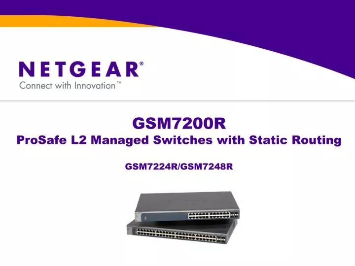
GSM7200R ProSafe L2 Managed Switches with Static Routing GSM7224R/GSM7248R. Section 1: Course Introduction. Course Description. This course will cover product specifications, product features, hardware installation/administration of the GSM7200R series switches.

E N D
GSM7200RProSafe L2 Managed Switches with Static RoutingGSM7224R/GSM7248R
Course Description • This course will cover product specifications, product features, hardware installation/administration of the GSM7200R series switches. • The course is intended for L1, L2, L3 technical support engineers, VARs and sales.
Course Objectives • Upon successful completion of this course, students will be able to answer basic questions about hardware specifications and features of the switches. • Example: • Hardware Features – How many ports are on each model of the switch? • Switch Features – Does the GSM7224R support RIP or OSPF? • Students will be able to physically install the hardware and initialize the switch for software management.
CoursePrerequisites • Attendees should have a basic understanding of OSI reference model and be familiar with standard layer2 and layer3 protocols. • Examples: 802.1Q, IGMP, STP, etc. • Software administration of the switches are covered by the 7000 series switches administration course.
Course Agenda • Section 1: Course Introduction • Section 2: Product Information • Section 3: Product Features • Section 4: Competitive Information (Not available at this time) • Section 5: Pre-install / Site Survey • Section 6: Hardware Installation • Section 7: Software Installation • Section 8: Software configuration (covered in Software Administration course) • Section 9: Testing the completed installation • Section 10: Troubleshooting
Product Description • The GSM7200R line of switches are gigabit, layer 2 managed switches with static layer 3 routing capability. In addition to a full layer 2 feature set, the administrator can enable routing on an interface or VLAN, and manage the routing table. • Dynamic routing protocols are not supported. Routing is controlled through static routing tables only.
Segmenting desktop environments for security or bandwidth control Because the GSM7200R performs both Layer 2 and Layer 3 functions, data traffic can be passed between attached VLANs without the need for an external router. Application – Layer 3 10.1.3.3 10.1.1.x/24 Redundant L3 fiber uplinks to the network core 10.1.4.5 10.1.2.x/24
7000 series switch family GSM7352S GSM7324 GSM7328S GSM7312 GSM7328FS FSM7352PS GSM7248R FSM7328PS Gigabit stackable layer 3 switches Gigabit layer 3 switches GSM7224R FSM7352S FSM7328S Gigabit layer 2 switches with static routing Fast Ethernet stackable layer 3 switches GSM7248 GSM7224 GSM7212 Gigabit layer 2 switches
Hardware features Each switch includes 4 gigabit copper/fiber combo ports. They are used to connect the switch to a high speed network using fiber optic cable.
Management features • Command line interface through serial console port, telnet, SSH(v1, v2) • Web graphical user interface through HTTP, HTTPS • RFC 2131 DHCP client (and BootP) • RFC 1757 RMON groups 1,2,3,9 • SNMPv1, v2c, v3 • RFC 1213 MIB II • RFC 1215 SNMP traps • RFC 1493 Bridge MIB • RFC 1643 Ethernet Interface MIB • Private Enterprise MIB • RFC 2138 RADIUS client • Broadcast storm control • Port Mirroring support • RFC 2030 SNTP • Ping support • ARP support • Configuration file upload, download (TFTP and HTTP) • Runtime image download (TFTP and HTTP) • SYSLOG
Layer 2 features • 802.1Q static VLAN (up to 4K) • Protocol VLAN • 802.1p Class of Service (CoS) • 802.1d Spanning tree • 802.1w Rapid spanning Tree • 802.1s Multiple spanning Tree • 802.3ad Link aggregation (LACP) • 802.1x Port access authentication • 802.3x Flow control • IGMP v1, v2 snooping support
Layer 3 features • Port Routing • VLAN Routing • IP ACL • DiffServ QoS (RFC 2998) • DCHP, BootP relay • DHCP server • UDP Relay • ARP • IGMP querier
Section 4 Competitive Information(Not available at this time)
Package Contents • Switch • Power adapter cord • Rubber footpads for tabletop installation • Rubber caps for the SFP sockets • Rack-mounting kit • Null-modem serial cable (RS232) with 9-pin connector • Resource CD • Warranty and Support Card • Installation guide • ProSafe NMS100 Network Management System 30-day trial CD-ROM
Unpacking the hardware • Check the contents of the boxes to make sure that all items are presents before beginning the installation. • 1. Place the container on a clean flat surface and cut all straps securing the container. • 2. Unpack the hardware from the boxes. • 3. Remove all packing material. • 4. Make sure that all items are present. If any item is found missing or damaged, contact local NETGEAR reseller for replacement. • 5. Inspect the products and accessories for damage .Report any damage immediately.
Hardware Installation • 1. Select a location • 2. Install the switch • 3. Check the Installation • 4. Connect to Power and Check the LEDs • 5. Stack multiple switches (optional) • 6. Connecting a Redundant Power Supply (optional) • 7. Connecting equipments to the switch • 8. Connecting a console to the switch
1. Selection a Location • See site requirement for switch location. • The switch can be mounted in a standard 19-inch (48.26cm) rack, wall mounted, or left freestanding (placed on a table top). • The site where you install the switch may greatly affect its performance. Before installing the switch, make sure that the chosen installation location meets the site requirements.
2. Install the switchInstall the switch on a flat surface • The switch ship with four self-adhesive rubber footpads. • Stick one rubber footpad on each of the four concave spaces on the bottom of the switch. • The rubber footpads cushion the switch against shock and vibrations.
2. Install the switchInstall the switch in a rack • 1. Attach the supplied mounting brackets to the side of the switch. • 2. Use the provide Phillips head screws to fasten the brackets to the side of the switch. • 3. Tighten the screws with a No.1 Phillips screwdriver to secure each bracket. • 4. Align the bracket and rack holes. Use two pan-head screws and nylon washers to fasten each bracket and to the rack. • 5. Tighten the screws with a No.2 Phillips screwdriver to secure the switch in the rack.
3. Check the installation • Before apply power, perform the following checks: • 1. Inspect the equipment thoroughly. • 2. Verify that all cables are installed correctly. • 3. Check cable routing to ensure that cables are not damaged and will not create a safety hazard. • 4. Be sure that all equipment is mounted properly and securely.
4. Connect to power and check the LED • The switch does not have an ON/OFF switch. The only way to apply or remove power is to connect or disconnect the power cord. Before connecting the power cord, select an AC outlet that is not controlled by a wall switch (which can turns off power to the switch). • 1. Connect one end of the AC power adapter cable to the rear of the switch, and the other end to a grounded three-pronged AC outlet. • 2. Check the Power LED on the front panel of the switch. The LED should light up in the following sequence: • The LED turns yellow as the switch run a Power-On-Self-Test (POST). • The switch passes the test, the LED turns green and the switch is working and ready to pass data. • If the POST fails, the Power LED blinks yellow.
5. Connecting SFP Modules • The module bay accommodates a standard SFP module with an LC connector that is compatible with IEEE 802.3z 1000BASE-X standard. • SFP modules are sold separately. • To install an SFP module, insert the SFP module into the module bay. Press firmly to ensure that the module seats into the connector.
6. Connecting a Redundant Power Supply (optional) • The GSM7200R switches have a redundant power supply connector in the back. • You can connect a DC-to-DC power supply to the switch in case the primary power supply fails. • To connect a RPS to the switch: • 1.Turn off the switch. • 2. Connect the RPS to the switch. • 3. Once all connections are completed, apply power to the switch. • Netgear do not manufacture RPS system at this time. For RPS that is compatible with Netgear switches, check Optimal Power at www.optimal-power.com.
7. Connecting equipments to the switch • RJ45 port: • The switch use Auto Uplink technology which enable you to attach devices using either straight-through or crossover cables. • Gigabit module bay: • Four ports on the switch can be used for either STP (RJ-45) or SFP (fiber) cable. However, both port types cannot be used at the same time. If both connectors are plugged, the SFP interface operates normally and disable the copper interfaces. • GBIC module currently supported: Netgear AGM731F, AGM732F, AGM733.
8. Connecting a console to the switch (optional) • 1. Connect the null-modem cable to the console port of the switch. • 2. Connect the other end of the cable to a workstation or terminal. • 3. If you attach a workstation, start a terminal-emulation program. • Microsoft window user can use Hyper Terminal which comes with Window 2000 and Window XP. Window Vista user need to install their own terminal-emulation program such as Tera Term. • 4. Configure the terminal-emulation program to use the following settings: • Baud rate: 9600 bps • Data bit: 8 • Parity: None • Stop bit: 1 • Flow Control: none
Section 7: Software Installation/Update Process *Software Update Process is covered by 7000 series switch software administration training
Initialize switch for management • Switch can be managed using web interface or CLI. • CLI can be accessed through serial console cable, telnet and SSH. • Web Interface can be accessed through HTTP or HTTPS. • To manage the switch over network, network connectivity must be established between the switch and the computer where the switch is being administered. Procedure to establish the connection depends on the IP addressing environment (assuming the switch is in factory default state): • 1. Computer in DHCP client mode but no DHCP server present. • 2. Computer with static IP address • 3. Computer in DHCP client mode with DHCP server present.
1. Computer in DHCP client mode but no DHCP server present • If no DHCP server present, the switch assume a default IP address of 169.254.100.100 and a subnet mask of 255.255.0.0. • The switch is in the same subnet used by a PC NIC port when in DHCP-client mode without a DHCP server present. • Use 169.254.100.100 to log into the switch using web server or CLI using telnet.
2. Computer with static IP address • If computer has static IP address, the switch must be assigned a static IP address in the same subnet through the console. • 1. Connect the PC’s to the console port of the switch to access the CLI through console. (See Section 5: Hardware Installation – connect a console to the switch) • 2. From the CLI, enter “admin” as user name and just hit the enter key when prompt for password. Type “ezconfig” and enter. • 3. Following the instructions and when prompt for IP address, enter an IP address in the same subnet as the computer. • 4. Use the assigned IP address to access the web GUI or CLI using telnet.
3. Computer in DHCP client mode with DHCP server present. • By default, the switch is configured as a DHCP client to obtain its IP address from a DHCP server in the connected network. • 1. Make sure that the switch is connected to a DHCP server. • 2. Find the switch IP address assigned by the DHCP server. • Connect the computer the switch’s console port (See Section 5: Hardware installation: Connect a console to the switch) • From the CLI, enter “admin” as user name and just hit the enter key when prompt for password. • Type “enable” and enter. When prompt for password, just hit enter. • At the next prompt, type “show network” and enter. • A screen will display and shows the active switch IP address. • 3. Use the switch IP address to access the web GUI or CLI using telnet.
Section 8: Software Setup / Configuration *This is cover in the 7300 series switches software administration training.
Testing the completed installation • 1. Check to make sure all equipments are mounted properly and securely. • 2. Check all cables are attached securely. • 3. Apply power to the switch while observing from the console. Verify the switch boot up to the user login prompt without displaying any error message or warning. • 4. Test network connectivity between devices connected to the switch. • 5. Verify switch’s management interface is accessible from either web GUI or telnet.
FAQ#1 - How to reset the switch to factory default without logging in first (e.g. user forget the password) • Power cycle the switch while accessing the console. • When the console display the boot menu option, enter 2. • Select option 10 to restore the configuration to factory default. • Select option 1 to boot up the switch. Note: All existing configuration will be lost.