Download
1 / 40
420 likes | 517 Views
This comprehensive report outlines the opto-mechanical design principles, requirements, and preliminary tests of a field integral spectrograph. Details include optical component specifications, alignment tolerance, and unit dimensions, emphasizing compatibility with low temperatures and ease of fabrication. The design covers the optical scheme, support interfaces, and material choices for optimal performance. Various unit descriptions, including the steering mirror, spectrograph, and detector units, along with the necessary components and adjustments, are explained in detail. The report concludes with a focus on the precision of unit positioning and alignment accuracy to meet the project goals efficiently.

E N D
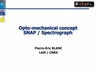
Integral Field Spectrograph Opto-mechanical concepts PIERRE KARST, JEAN-LUC GIMENEZ CPPM(CNRS),FRANCE
Summary • Requirements • General design • Opto-mechanical mount principle • References definition • Description of the units • Optical baffling studies • Cold test : preliminary lay out • Conclusion Pierre KARST
Requirements 1/2 • Optical scheme : Beam geometry and active surfaces of the optical components • = 350 to 1700 nm : Visible and IR detectors • Respect of the alignment tolerance from 300 to 100 K • Adjustment of the optical components and the detectors • Optical components made of Zerodur (mirror) and BK7 (prism) Pierre KARST
Requirements 2/2 • Alignment tolerance Detector unit Steering mirror unit Spectrograph unit GENERAL REQUIREMENT: COMPONENT X = Y= Z= ± 0,1 mm Tilt Ox= Oy = ± 5 arcmin UNIT X = Y= Z= ± 0,2 mm Tilt Ox= Oy = Oz = ± 5 arcmin Slicer unit X = Y= Z= ± 0.02 mm Offner relay unit Bench Pierre KARST
General design 1/5 Overview Steering mirror unit Spectrograph unit Detector unit Bench Support of the units Interface with external devices Slicer unit Offner relay unit Pierre KARST
General design 2/5 • Overall dimensions with the IR detector 420 mm 210 mm 630 mm Pierre KARST
General design 3/5 Slicer and spectrograph region (# SNAP spectro) 95 mm 160 mm 270 mm Pierre KARST
General design 4/5 • Visible test at room temperature Illumination module of the Proto 0 Demonstrator Optical table Support Pierre KARST
General design 5/5 Choice material trade off: Compatibility with vaccum at low temperature (100 K) compatibility with Zerodur (Low CTE) Good alignment in the temperature range (300-100K) Good thermal properties high Young modulus Short allowed time = easy fabrication Low cost Pierre KARST
Opto-mechanical mount principle 1/6 Optical components : Rectangular mirror, Zerodur, 110x30x20 Cylindrical mirror, Zerodur, 26 to 34x10 Prism, BK7, mean thickness 10 mm, 26x26 Mount components : Frame and positioning parts, Invar. Clamping and screws : TBD Requirement in the range 300 to 100 K : Positioning tolerance : ± 0.1 mm ± 5 arcmin Pierre KARST
Opto-mechanical mount principle 2/6 • Cylindrical mirrors : Elastic clamping Plan contact with 3 points Mirror mount Mirror Centering with 2 small machined plans Support Pierre KARST
Opto-mechanical mount principle 3/6 Rectangular mirror: Plan contact Spring plungers Punctual contact Orientation Elastic clamps Mirror Pierre KARST
Opto-mechanical mount principle 4/6 • Mirror mount positioning: Spring plungers for the alignment Screws for fixation Stopper Pierre KARST
Opto-mechanical mount principle 5/6 6 elastic clamps Prism 6 small pads • Prism mount: 3 rotations are required. Positioning by 3 axis and screws on cantilever. Pierre KARST
Opto-mechanical mount principle 6/6 • Prism mount: Position adjustment Y adjustment Z adjustment Centering of the axis < 10 mm Accuracy of the angular adjustment < 3 arcmin Y Z Spring plunger X adjustment mm screw X Pierre KARST
References definition 1/2 Y Z Z Y Z Z Y Y O Z Y General reference: Active surface positions Origin = Slicer reference Pierre KARST
References definition 2/2 Active surface Positioning and measurement of the actives surfaces respecting to the Unit reference Supporting surfaces of the mount Positioning surfaces of the mirror External surfaces Unit reference • Accuracy of reference transfer with a CMM < 10 mm • Positioning of the active surface < 40 mm (Alignment tolerance = ± 0.1 mm) Pierre KARST
Description of the units 1/8 Travel along the beam Detector unit Bench Spectrograph unit Offner relay unit Steering mirror unit Slicer unit Pierre KARST
Description of the units 2/8 Steering mirror support unit Steering mirror envelop Titanium support Outgoing beam X Incoming beam Z Pupil aperture Y Contact plan Locating hole Shrinkage around the vertex of the mirror Centering hole Pierre KARST
Description of the units 3/8 Slicer unit Incoming beam Pupil mirrors Stack of slices Outgoing beam Slit mirrors X Z Y Pierre KARST
Description of the units 4/8 Slicer unit Slice mirrors support Box and cover Made of Invar Mirror supporting blocks Made of Zerodur Mirror supporting blocks Made of Zerodur Pupil and slit mirror support The Zerodur assembly will be held by elastic clamps (TBD) Pierre KARST
Description of the units 5/8 Stopper Orientation X Y Z Plan contact Spectrograph unit Outgoing beam Camera mirror Collimator mirror Prism Incoming beam Pierre KARST
Description of the units 6/8 Offner relay unit Offner primary mirror Plane mirror Detector focal plan Stopper Orientation X Z Y Incoming beam Offner secondary mirror Plan contact Pierre KARST
Description of the units 7/8 Fixation Contact plan Visible detector X Z Y Pierre KARST
Description of the units 8/8 Stopper Orientation Contact plan Unit interface Cone Groove Flat Bench • Support of the unit • Connection to the external devices • Keeps the alignment specification (stiffness and thermal fluctuation) Pierre KARST
Optical baffling studies Pierre KARST
Cold test: preliminary lay out 1/5 • Specific requirement: Vacuum < 10-5 mbar Existing cryostat External illumination source unit: view port T° demonstrator < T° IR detector IR detector requirement: • T° = 120 ± 5 K, stability 0.5 K • Temperature fluctuation max < 1K/minute • 1 short signal cable (20 cm) connected to a electrical board at room temperature Diameter 180 mm 60 mm Pierre KARST
Cold test: preliminary lay out 2/5 Herschel cryostat • View port • Several available feedthroughs for the electrical output. • Clean room • It is equipped with two cryonegic heads Pierre KARST
Cold test: preliminary lay out 3/5 Overview Viewport Signal cable feedthrough Cryogenic devices Pierre KARST
Cold test: preliminary lay out 4/5 • Overview avant le detecteur Signal cable Thermal baffling Pierre KARST
Cold test: preliminary lay out 5/5 • IR detector on the demonstrator Bench IR detector support Pierre KARST
Conclusion • This preliminary design meets the requirements • Next steps, we have: - To finish the slicer unit concept - To detail the thermal studies - To define the optical baffling - To adapt the bench to the interfaces and thermal constraints Pierre KARST
Spares • Cut view of the mirror mount • Alignment benches • Herschel cryostat dimensions • Mechanical description of the visible detector • Slicer unit • Shrinkage Pierre KARST
Alignment bench : spectrograph unit Pierre KARST
Alignment bench : Offner relay unit Pierre KARST
Cylindrical mirror mount Pierre KARST
Spares Herschel cryostat : Dimensions Pierre KARST
Visible detector Mechanical description Pierre KARST
SLICER UNIT SLICER UNIT Pierre KARST
Tolerance for adjustment at room T° Pierre KARST