Download
1 / 29
290 likes | 448 Views
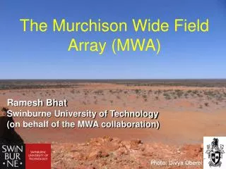
The Murchison Wide Field Array (MWA). Ramesh Bhat Swinburne University of Technology (on behalf of the MWA collaboration). @ Murchison, ~300 km from Geraldton. The Partnership. MIT Haystack Observatory (Project Office) MIT Kavli Institute Harvard Smithsonian Center for Astrophysics

E N D
The Murchison Wide Field Array (MWA) Ramesh BhatSwinburne University of Technology(on behalf of the MWA collaboration)
The Partnership • MIT Haystack Observatory (Project Office) • MIT Kavli Institute • Harvard Smithsonian Center for Astrophysics • UMelbourne, Curtin Uni, Aus Nat Uni • USydney, UTasmania, Uni Western Aus • ATNF CSIRO (via synergy with ASKAP) • Raman Research Institute, India 3
MWA Science Goals • Epoch of Reionization • Power spectrum • Strömgren spheres • Solar/Heliospheric/Ionospheric Science (SHI) • Solar imaging • Faraday rotation – B field of CME’s and heliosphere • Interplanetary Scintillation • Small scale ionospheric structure • Transients • Deep blind survey • Light curves (field and targeted) • Synoptic surveys • … • Other • Galactic and Extra-galactic astronomy • Pulsars • ISM survey • Recombination lines • ...
Epoch of Reionisation (EOR) • After ~300,000 years electrons and protons combine to form hydrogen • After ~1 billion years stars and quasars ignite, radiation splits hydrogen into protons and electrons. • In between are the Dark Ages
MWA Science Goals Epoch of Reionization Power spectrum Strömgren spheres Solar/Heliospheric/Ionospheric Science (SHI) Solar imaging Faraday rotation – B field of CME’s and heliosphere Interplanetary Scintillation Small scale ionospheric structure Transients Deep blind survey Light curves (field and targeted) Synoptic surveys … Other Galactic and Extra-galactic astronomy Pulsars ISM survey Recombination lines ...
Array Configuration 1.5 km 1.5 km 120 m 500 m
Crab giant pulse detections with the ED system System: 3 tiles - G ~ 0.01 K/Jy Tsys ~ 200 + 180 K BW ~ 0.75 x 8 MHz Freq = 200 MHz # GPs ( > 9 kJy) = 31 Bhat, Wayth, Knight, et al. (2007), ApJ, 665, 618
Giant pulse and (fast) transient detection prospects with MWA Bhat et al. (2008)
32 Tile Prototype • Motivation • Engineering test bed • End to end signal/data path and system performance testing • Training data sets for calibration system • Learning to operate in the site conditions • Early Science
32 Tile system: Specs Aperture plane uv plane
6 Tile system 6 tiles from the 32 available First field testing of the prototype receiver Bandwidth – 1.28 MHz Offline software correlation Essentially arbitrary spectral and time resolution – Extremely well suited for imaging of solar bursts
Early 6T results Phase (deg) 1.28 MHz Time (4 hrs) uv coverage Amplitude band shapes Closure Phase Phase band shapes
Real time system for calibration and imaging: signal processing challenges • Data volume - 19 GB/s • Raw visibility cannot be stored • Dedicated hardware for correlation and data processing • Large FOV • Wide FOV requires new approach to integrating, imaging (and deconvolution) • Gain and polarisation responses are direction dependent • Calibration • Must be real time, since visibilities are not stored • Ionosphere shifts source positions by ~arcminutes • Ionosphere should be a phase ramp over array • Ionospheric faraday rotation
MWA RTS - The Imaging pipeline Mitchell, Greenhill, Wayth, et al. (2008), IEEE
Real time system: Computational costs • Parameters (8 second cadence): • 40 peel sources, 400 iono sources • 1125^2 image size (primary beam) • 768 frequency channels, 130000 visibilities • Calibration: 3.3 Tflop • Grid and image: 1.8 Tflop • Stokes conv: 4.3 Tflop • Regridding: ? (0.05 to 28 Tflops) • Approx total: 10 Tflop (efficient regrid) (over 8 seconds)
User access to the MWA • Not an open facility - as originally proposed • Some partners have proposed a “user facility” • Current policy - Interested pulsar users are welcome to join the collaboration • Pulsar science - part of the transient science collaboration - coordinators: Roger Cappallo (MIT) and Shami Chatterjee (Univ. Syd) • Current (pulsar) members: Bhat, Bailes, Deshpande
Concluding Remarks MWA - a major low frequency instrument in the southern hemisphere Status: 32T system by Q4 2008, full system by 2009 Primary science: EOR, transients, solar A great instrument for pulsars (G ~ 3 K/Jy) Early pulsar science - Crab giants @200 MHz Interested users are welcome to join the collaboration (transients + pulsars)