Download
1 / 22
220 likes | 457 Views
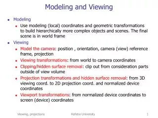
ME 501 Final Project: Analysis of Ford Expedition Frame Crossmember. June 20, 2001 John Smart Andy Stansel. Courtesy Ford Motor Company Used without permission. Presentation Outline. Project Background and Objective Modeling—meshing, boundary conditions. 3 loading conditions Results

E N D
ME 501 Final Project:Analysis of Ford Expedition Frame Crossmember June 20, 2001 John Smart Andy Stansel Courtesy Ford Motor Company Used without permission
Presentation Outline • Project Background and Objective • Modeling—meshing, boundary conditions. • 3 loading conditions • Results • Conclusions
Modeling—ProE Model New crossmenber dimensions OEM Crossmember New crossmember Frame rails • Both crossmembers were created in Pro/E
Modeling—Ansys Model • Export Pro/E model as an IGES file • Import the IGES file into ANSYS • Set element type as “Shell 63” (3D, 4 node element, 6 DOF per node) • Set shell thickness to .125” • Material properties of steel (E=30 Mpsi, n=.27)1040 Steel, Sy = 86 kpsi
Modeling—Meshing Coarse & fine free meshing 4 elements thick • Several different meshes were tested Fine mapped meshing 2,544 elements 2,546 nodes 15,276 DOF (unconstrained)
Modeling—Boundary Conditions #1 Fixed symmetry #2 Chase boundary OEM crossmember • Two separate boundary conditions were tested Difference of 8 kpsi
Modeling—Boundary Conditions #1. Fixed, fixed #2. Quasi-simply supported Difference of 2 psi! Therefore, we used fixed-fixed conditions New crossmember • Two separate boundary conditions were tested
Loading Condition #1 OEM crossmember New crossmember 1,000 lbs. Fixed Rollers 1,000 lbs 1,000 lbs. Fixed Fixed • Vehicle at rest, or driving straight, or landing from jump.
Loading #1— Results OEM crossmember New crossmember Maximum deflection=.022” Maximum deflection=.0335” Y-displacement Bulges out here
Loading #1— Results OEM crossmember New crossmember Max eq. stress: 47 kpsi Factor of safety: 1.8 Max eq. stress: 34 kpsi Factor of safety: 2.5
Loading Condition #2 OEM crossmember New crossmember fixed fixed 500 ft-lbs 500 ft-lbs • Frame rails twist due to terrain. This induces torsion in the crossmember.
Loading #2—Results OEM crossmember New crossmember Max deflection: 0.0308” Max deflection: 0.0325”
Loading #2—Results OEM crossmember New crossmember Max eq. stress: 7.6 kpsi Factor of Safety: 11.3 Max eq. stress: 8.8 kpsi Factor of Safety: 9.7
Loading Condition #3 1,000 lbs 1,000 lbs fixed fixed • Pure bending in crossmember OEM crossmember New crossmember
Loading #3—Results OEM crossmember New crossmember Max deflection: 0.897” Max deflection: 0.972”
Loading #3—Results OEM crossmember New crossmember Mad stress concentration Max eq. stress: 59.1 kpsi Factor of safety: 1.4 Max eq. stress: 92.8 kpsi Factor of safety: 0.92
Loading #3—Results sZ (normal) OEM crossmember New crossmember Neutral axis
Model Limitations • Difficult to model frame rail interaction—boundary conditions • Difficult to know magnitude of loading conditions • No detailed models of weld joints, body mounts, gussets, or rounds
Conclusion Our simple analysis shows: • The new crossmember is less stressed than the OEM version for typical “around town” loading conditions (load case 1) • However, for extreme off-road type load conditions, the new crossmember is inferior to the OEM (load cases 2,3) • Further analysis and prototype testing should be done before going into production.
What we learned • 3D importing • 3D meshing • Effects of different boundary conditions • FEA is not a “black box”