Download
1 / 27
270 likes | 292 Views
Explore the structure of atoms, the movement of electrons, and the fundamentals of electricity. Learn about conductors, insulators, voltage, resistance, and more.

E N D
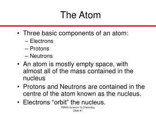
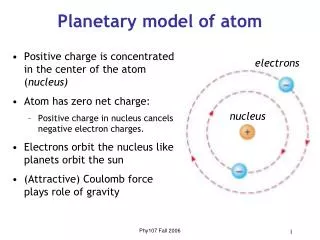
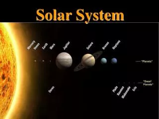
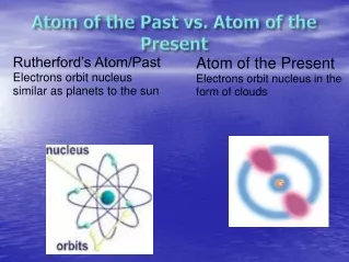
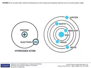
FIGURE 3-1 In an atom (left), electrons orbit protons in the nucleus just as planets orbit the sun in our solar system (right).
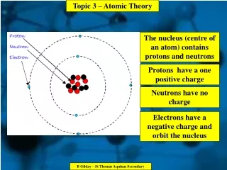
FIGURE 3-2 The nucleus of an atom has a positive (+) charge and the surrounding electrons have a negative (-) charge.
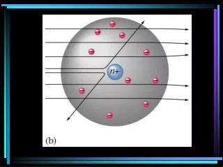
FIGURE 3-5 An unbalanced, positively charged atom (ion) will attract electrons from neighboring atoms.
FIGURE 3-6 The hydrogen atom is the simplest atom, with only one proton, one neutron, and one electron. More complex elements contain higher numbers of protons, neutrons, and electrons.
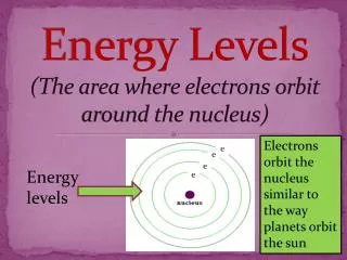
FIGURE 3-7 As the number of electrons increases, they occupy increasing energy levels that are farther from the center of the atom.
FIGURE 3-8 Electrons in the outer orbit, or shell, can often be drawn away from the atom and become free electrons.
FIGURE 3-9 A conductor is any element that has one to three electrons in its outer orbit.
FIGURE 3-10 Copper is an excellent conductor of electricity because it has just one electron in its outer orbit, making it easy to be knocked out of its orbit and flow to other nearby atoms. This causes electron flow, which is the definition of electricity.
FIGURE 3-11 Insulators are elements with five to eight electrons in the outer orbit.
FIGURE 3-12 Semiconductor elements contain exactly four electrons in the outer orbit.
FIGURE 3-13 Current electricity is the movement of electrons through a conductor.
FIGURE 3-14 Conventional theory states that current flows through a circuit from positive (+) to negative (-). Automotive electricity uses the conventional theory in all electrical diagrams and schematics.
FIGURE 3-15 One ampere is the movement of 1 coulomb (6.28 billion billion electrons) past a point in 1 second.
FIGURE 3-16 An ammeter is installed in the path of the electrons similar to a water meter used to measure the flow of water in gallons per minute. The ammeter displays current flow in amperes.
FIGURE 3-17 Voltage is the electrical pressure that causes the electrons to flow through a conductor.
FIGURE 3-18 This digital multimeter set to read DC volts is being used to test the voltage of a vehicle battery. Most multimeters can also measure resistance (ohms) and current flow (amperes).
FIGURE 3-19 Resistance to the flow of electrons through a conductor is measured in ohms.
FIGURE 3-20 A display at the Henry Ford Museum in Dearborn, Michigan, that includes a hand-cranked generator and a series of light bulbs. This figure shows a young man attempting to light as many bulbs as possible. The crank gets harder to turn as more bulbs light because it requires more power to produce the necessary watts of electricity.
FIGURE 3-21 Electron flow is produced by heating the connection of two different metals.
FIGURE 3-22 Electron flow is produced by light striking a light-sensitive material.
FIGURE 3-23 Electron flow is produced by pressure on certain crystals.
FIGURE 3-26 A three-wire variable resistor is called a potentiometer.
FIGURE 3-27 A two-wire variable resistor is called a rheostat.