Download
1 / 34
450 likes | 622 Views
Chapter 4 - Electricity. Foundation of Physical Layer. Physical Layer Function. Transmit data by defining electrical specifications between source and destination Electricity carried to workstations, servers, network devices via wires

E N D
Chapter 4 - Electricity Foundation of Physical Layer
Physical Layer Function • Transmit data by defining electrical specifications between source and destination • Electricity carried to workstations, servers, network devices via wires • Data travels through wires and is represented by presence of absence of electrical pulses or light pulses
Why Learn Electronics • Most of the devices and processes involved in networking are electronic • Anyone installing cable must have an awareness of conducting paths, short circuits, and open circuits • Extensive use of frame, packet, and segment format diagrams is based on voltage versus time diagrams of oscilloscope or logic analyzer
Everything You Wanted To Know About Atoms • Nucleus – center • Proton – particles that have positive charge • Neutrons – particles that have no charge; form nucleus when combined with protons • Electrons – particles that have a negative charge and orbit the nucleus
Did You Know That • Electrons can “come loose” from atoms • This explains electrical conduction in solids • Opposite charges react to each other • They are attracted to each other • The force increases as charges move closer
Questions • Why don’t electrons fly in to the center? • They stay in orbit because they have just enough velocity to keep orbiting • Why don’t protons fly apart? • A nuclear force acts as a kind of glue to hold them together • What causes electricity? • Electrons can be pulled from from the atom and pulled free from the atom and made to flow
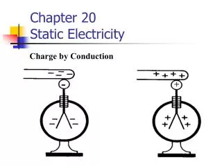
ESD – Electrostatic Discharge • Static Electricity – electrons at rest – loose but stay in one place • Can jump if given opportunity • Harmless to people • Dangerous to computers & computing equipment • Randomly damage computer chips or data
Computing Devices/Current Flow • Control electrons using • Conductors – copper paths • Semiconductors • Insulators • Plastic or rubber
Materials • Insulators - Allow electrons to flow through them with great difficulty, or not at all (high resistance) • Glass, plastic, wood, air • Conductors - allow electrons to flow through them with great ease • Copper, silver, gold • Semiconductors - amount of electricity they conduct can be precisely controlled • Silicon, carbon, gallium arsenide
Terms • Voltage (Electromagnetic Force) V • electrical force, or pressure, that occurs when electrons and protons are separated. • Electrical Current I • flow of charges that is created when electrons move • Resistance R • varying amounts of opposition to flow of electrons • Measured in OhmsW
Current • The measurement of electron flow in electrical circuits • AC (Alternating) • Polarity changes; terminals reverse polarity or direction • DC (Direct) • Always flows in same direction; one terminal is always positive and the other is always negative • Impedance • total opposition to current flow Z • Measured in Ohms W
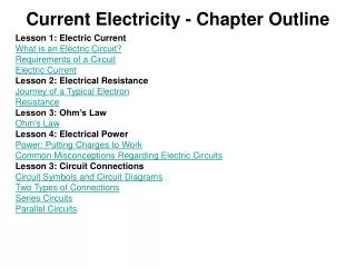
Circuits • Currents only flow in closed loops (complete path) called circuits • Must be composed of conducting materials • Must have source of voltage (power, e.g. battery) and load or resistance
Grounds • Reference Point or 0 voltage level • Place on earth where current goes into ground • Safety ground wire connected to chassis (exposed metal case) • prevent metal parts from becoming energized with a hazardous voltage resulting from a wiring fault
Protection Devices • Circuit Breakers • Interrupt the circuit and stop the flow of electrons • Ground Fault Circuit Interrupters • Same as Circuit Breakers • Surge Suppressors • Protect against spikes • UPS (Uninterrupted Power Supply) • Take over when there is power outage
Using the Multimeter • Measures voltage, resistance, and continuity • Set meter to DC when measuring • Batteries • Solar cells • DC generators • Computer power supplies • Set meter to AC when measuring • Wall sockets • 120 V in USA and 220 V around the world • Remember – line voltage can kill
Analog Signal • Is wavy • Has a continuously varying voltage-versus-time graph • Is typical of things in nature • Has been widely used in tele-communications for over 100 years • Measured by amplitude and time
Digital Signal • Has discrete, or jumpy, voltage-versus-time graphs • Is typical of technology, rather than nature • Fixed amplitude • Can be approximated with square wave with seemingly instantaneous transitions between high and low • Square wave can be built using right combination of many sine waves (Fourier)
Binary Digit • Building Block of data communication system • Could be +5 V for 1 and 0 V for 0 • Low or no light for 0 and high intensity for 1 • Short wave burst for 0 and long wave burst for 1 • Signal reference ground must be close to computer’s digital circuits • Designed into circuit boards • Remember – 8 bits = 1 byte
Bit Events • Propagation • Attenuation • Reflection • Noise • Timing Problems • Collision
Propagation • A lump of energy, representing 1 bit, travels from one place to another • Speed depends on the actual material used in the medium, the geometry (structure) of the medium, and the frequency of the pulses. • Round Trip Time - time it takes the bit to travel from one end of the medium and back again • Extremes • 0 time to travel • Forever to travel • May have to buffer to accommodate differences
Attenuation • Loss of signal strength, possibly due to distance traveled • Material and geometry can reduce attenuation • Optical Signals • Minimize by color or wavelength used • Or by single or multi-mode fiber • Or by type of glass filament used • Radio Waves Can be absorbed or scattered by atmospheric molecules
Solving Attenuation Problems • Select media carefully • Choose structures with low rates of attenuation • Use a repeater after a certain distance
Reflection • Results from impedance mismatch • Small part of pulse returns to you • Energy reflected can interfere with bits following in the data stream • Correct impedance can solve reflection and interference problems
Noise • AC Power and reference ground – big problem • AC line noise is all around us • Power line noise can cause network problems • Problems with the power ground can lead to interference with the data system • Long neutral and ground wires can act as an antenna for electrical noise. It is this noise that interferes with the digital signals (bits)
Noise Sources • Video monitor • Hard disk drive • Electric motor • Other Wires
So Why Twisted Pairs? • Crosstalk is a form of electrical noise that results from signals from other wires • Solution is Twisting the pairs of wires – see curriculum for details on how it works
EMI/RFI • External Noises • Lighting, electrical motors, and radio systems • Each wire in a cable can act like an antenna • Most LANs use frequencies in the 1-100 megahertz (MHz) frequency region • So do radio, TV, and appliances
Noise Caveats • Optical fiber is immune to NEXT and AC power/reference ground noise • Wireless systems are particularly prone to EMI/RFI • The problem of NEXT can be addressed by termination technology, strict adherence to standard termination procedures, and UTP • Can install a power transformer to serve only the area covered by the LAN
Jitter, Dispersion, and Latency • All affect the timing of a bit • Dispersion - signal broadens in time • can be fixed by proper cable design, limiting cable lengths, and finding the proper impedance • Jitter – clock on host and destination are not synchronized • Latency – aka Delay of network signals • bit takes at least a small amount of time to get to where it’s going • Network devices add more latency
Why Timing is Important • Network speeds today 1 Mbps to 155 Mbps • Speed will be 1 Gbps • Dispersion can cause 0 to be mistaken for 1 • Jitter can cause problems as messages are assembled by destination computer • When bits are late, network devices can get overwhelmed
Collision • Two bits from two different communicating computers are on a shared-medium at the same time • Two voltages are added & cause a higher voltage level (not allowed in binary system) • Bits are destroyed • Excessive collisions can slow down a network • Require a set of rules to deal with event or • Allow only one computer to transmit at a time (token)
Encoding • Converting binary data into a form that can travel on a physical communications link • voltages on various forms of copper wire • pulses of guided light on optical fibers • modulated, radiated electromagnetic waves. • Modulation - using the binary data to manipulate a wave.
Encoding Schemes • NRZ encoding and Manchester encoding. • NRZ (non-return to 0) encoding is the simplest • high signal and a low signal (often +5 or +3.3 V for binary 1 and 0 V for binary 0 • Manchester - more complex, but is more immune to noise and is better at remaining synchronized • results in 1 being encoded as a low-to-high transition and 0 being encoded as a high-to-low transition
Encoding Messages • As voltages on copper; Manchester and NRZI encoding are popular on copper-based networks • As guided light; Manchester and 4B/5B encoding are popular on fiber based networks • As radiated EM waves; a wide variety of encoding schemes are used on wireless networks