Mold Information
Mold Information. Mold Specification. Please give your approval and comments. Page 1. Part Size. 218.881mm. 219.693 mm. 651.576 mm. 651.576 X 218.881 X 219.693mm. Data name: TUNNEL_INNER_SHELL_________________-_13N0169CP__01_140514_FS1ARFR.CATPart. Page 2. Layout. TOP OF MOLD.
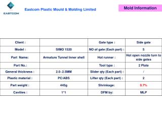

Mold Information
E N D
Presentation Transcript
Mold Specification Please give your approval and comments Page 1
Part Size 218.881mm 219.693 mm 651.576 mm 651.576 X 218.881 X 219.693mm Data name: TUNNEL_INNER_SHELL_________________-_13N0169CP__01_140514_FS1ARFR.CATPart Page 2
Layout TOP OF MOLD LIFTER LIFTER OperatOR SIDE 2 - plate mold with hot open nozzle turn to side gate Page 3
Gate type 2-plate mold with hot runner. Hot open nozzles edge gates 1.5x10mm Page 4
Core Parting line P/ LINE PL Cavity Page 5
Core Parting line P/ LINE PL Cavity Page 6
Parting line P/ LINE Cavity PL Core Page 7
Cavity Parting line P/ LINE PL Core lifter line Page 8
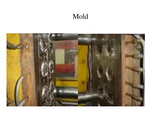
Cavity insert Cavity insert pin Cavity insert Page 9
Cavity insert Core insert Page 10
Draft angle The green surfaces arrowed are straight in the direction of demolding. Is it possible to add 2 degree draft by reduce material? If OK, please send update part drawing to us. Page 11
Draft angle The green surfaces arrowed are straight in the direction of demolding. Is it possible to add 2 degree draft by reduce material? If OK, please send update part drawing to us. Page 12
Draft angle The green surfaces arrowed are straight in the direction of demolding. Is it possible to add 2 degree draft by reduce material? If OK, please send update part drawing to us. Page 13
Draft angle We would like to change these surface on the core side, and add 1 degree draft angle, because of we are worry about the part will stick on the cavity. If OK, please send update part drawing to us. Page 14
Draft angle R0.5mm We are worry about the part will stick on the cavity. Please confirm if we can add some undercut on the core side. If OK, please send update part drawing to us. Page 15
Ejector pin Ejector sleeve Ejector pin Page 16
Ejector pin We are worry about the part will stick on the cavity. Please confirm if we can add Air Poppet Valve on the cavity side. Page 17
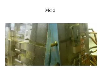
Thickness analysis There are slight shrinking mark on the red surface. Page 18
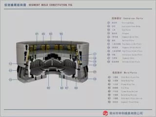
ID plate Core water line plate Cavity water line plate ID plate Page 19
Engraving If there are any engrave request on the part? Please advise.
Appearance Page 21 Page 21
Part Color Page 22 Page 22
Thank you Page 23